Tag Archives: straight gear

China Sgr Brand Inline Straight Planetary Gear Speed Reducer, Gearmotor, Gearboxes Coupled with ABB Hydraulic Motor planetary gearbox buy online

Product Description

Solution Description
SGR planetary gear motor 
Complex knowledge:
1. Ratio variety: 8.1-191
two. Enter electrical power: .twelve-270 KW
3. Permit torque rang: ≤ 50000 N. M
4. Output speed: .3~205 r/min
5. Structure: Foot-mounted, flange-mounted, shaft-mounted

Enter construction motor,IEC flange
Output speed strong shaft, hollow shaft with essential,with shrink disk

Characteristic:
one. Undertake optimized design and style, module combination, appropriate angle output, place reduction
two. Substantial toughness and longevity gears
3. Can be combined with a variety of motors, wider ratio variety
four. Big output torque, efficiently startup, substantial effectiveness
Creation photos:

Packing Pictures :

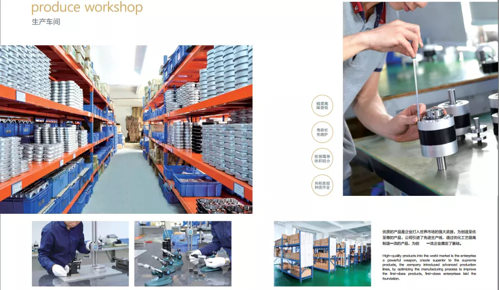
Manufacturing facility

———————————————————————————————————————————————
FAQ:

one.Are you a factory or trader ?
We are a skilled manufacturing unit which has 20 a long time background specialised in equipment transmission .

2.MOQ:
Our MOQ is 1pcs. Nevertheless there is 1 handling expense $one hundred fifty for the single order which significantly less than $3000.00

three. Warranty
Our guarantee is 12months

four. Payment expression
a hundred% T/T in progress and LC at sight .

five. Do you take customization ?
Indeed.SGR have robust R&D crew, we can provide customizable service according to demands.

six. Packing
Generally we use regular export plywood situation to prepare the shipment .

seven. Supply time
In standard ,time of supply is 30days following getting the prepayment .

eight. What sorts of certification do you use ?
DNV-ISO9001:2008, SGS,CE and so forth, And new merchandise patent.

nine. What kinds of inspection you do prior to cargo ?
We do temperature take a look at, noise, and oil leak inspection and commissioning just before shipment.

10.How do you fix if the manufacturing have difficulty ?
Primarily, we never want customer send the goods again to us. Due to the fact the expense is very substantial, if there fulfills a issue,we firstly ask for the photos for broken components. And base on the photographs, we can have a standard notion for the defect purpose. Our ensure is twelve months, if in the course of the ensure, we can source repair .  
 

US $200
/ Piece
|
1 Piece

(Min. Order)

###

Application: Motor, Machinery
Function: Distribution Power, Change Drive Torque, Speed Reduction
Layout: Coaxial
Hardness: Hardened Tooth Surface
Installation: Horizontal Type
Step: Single-Step

###

Samples:
US$ 200/Piece
1 Piece(Min.Order)

|
Request Sample

###

Customization:

###

Input structure motor,IEC flange
Output speed solid shaft, hollow shaft with key,with shrink disk

What is a Planetary Gearbox?

A planetary gearbox is a mechanical device in which the teeth of a planet mesh with the teeth of its sun or ring. The number of teeth and the spacing of planets will determine whether the teeth mesh correctly. In this article, we will learn more about planetary gearboxes. Besides understanding their working, you can also learn how to design your own. Here are some examples:

planetary gearboxes

If your car has an automatic transmission, then a planetary gearbox is the type you have. It is possible to find out if you have this type of gearbox by consulting the owner’s manual, calling the service department of your car’s manufacturer, or conducting a search using your favorite search engine. However, planetary gears are more complex and have many more components than standard gearboxes. The following information will explain more about this type of gearbox.
Planetary gearboxes use three different gear types to transmit torque. The sun gear sits in the center of the gear assembly, while the other gears rotate around it. A carrier connects the two gears, and is designed to set the spacing between them. When the gears are rotated, the carrier will spin, enabling the entire assembly to work together. The carrier also incorporates the output shaft. For this gearbox to work effectively, it must meet the application’s requirements.
There are three main types of planetary gearboxes: the basic model is highly efficient and transmits 97% of the power input. The earliest models are not complex, but they do have some key differences. Some of these differences make them ideal for various applications. For example, a planetary gearbox can operate in alternating and continuous operation, with the output support having internal grooving. Some designs have more than one output shaft, allowing the user to choose the configuration and torque that is best for their application.
One of the main differences between a planetary gearbox and a conventional one is the way the planetary parts move. A planetary gearbox may have multiple axes for increased torque. A planetary gearbox can provide a torque up to 113,000 N.m. by rotating its maximum teeth simultaneously. They are the ideal choice for space-constrained applications. For instance, a car with small spaces can install one with ease.
A planetary gearbox’s gear ratio is determined by the ratio of the sun gear to the ring gear. The number of teeth on the sun gear is a way to adjust the gear ratio. Smaller sun gears result in larger planetary gear ratios, while larger ones cause a decrease in torque. The ratio between planetary gears ranges from 3:1 to 10:1, with the lowest ratio being three. The greatest possible ratio is 10:1.
A planetary gearbox has many benefits. The compact design makes them a more efficient choice for small motors and is advantageous for servo functions. Planetary gearboxes have low inertia, which is an important factor, especially in servo applications, since the inertia of the gearbox adds to the motor’s load inertia. The planetary gearboxes are typically lubricated with grease or oil, so you don’t need to worry about re-lubrication or maintenance.
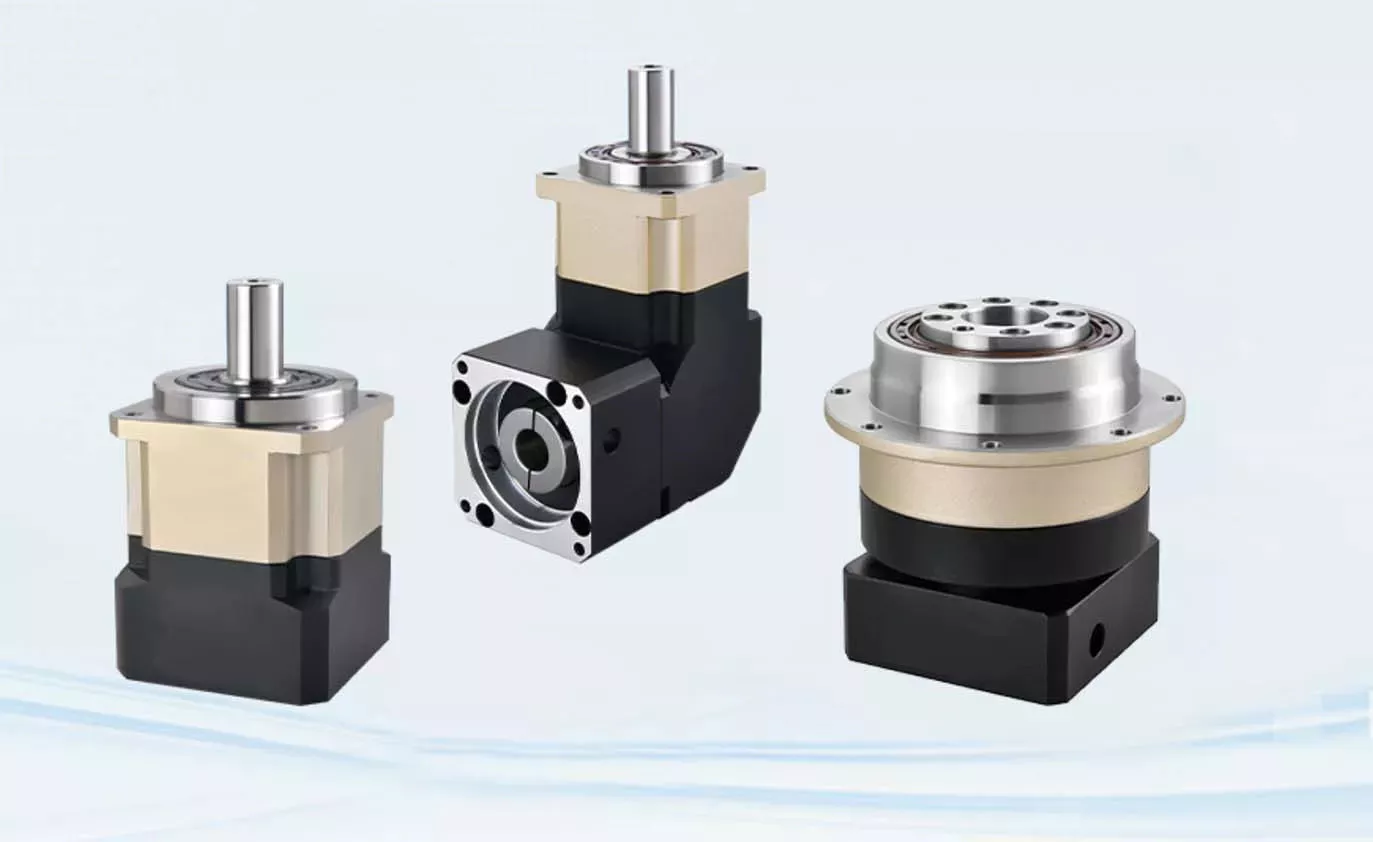
planetarygearbox

planetary gearboxes with output shaft

The advantages of planetary gearboxes are numerous. They are widely used in many applications, from automobiles to medical equipment, goods & personnel lifts to machine tools. They are also used in derrick & dockyard cranes and slewing drives. These gearboxes are available in various sizes and shapes, ranging from small to extremely large. There are many different types, and each is designed to suit its intended use.
The LP generation 3 gearhead series combines maximum quality with economic precision in a low-backlash planetary gearbox. The output shaft version is especially suited for high-speed, highly dynamic cyclic operation. Another version is the SP+ HIGH SPEED. The SP+ high-speed version is designed to achieve maximum speeds while in continuous operation. If you need a planetary gearbox with an output shaft, look no further. It is the best choice for many applications.
As the name suggests, a planetary gearbox incorporates planetary parts and an output shaft. The outer gears (also called the planetary gears) are connected by a carrier to the output shaft. The carrier is then connected to the output shaft by a ring. There are two or more planetary gears inside the planetary gearbox. Each gear is connected to a carrier, which is connected to the output shaft.
An epicyclic planetary gear train can be assembled so that the planet gear rolls around the sun gear. In the wheel drive planetary gearbox, the planetary gears are grouped over the housing to optimize the size and weight of the system. The planetary gear train can handle torques as high as 332,000 N.m., with the ring gear being fixed while the sun gear is movable.
Another advantage of a planetary gearbox is that it uses many teeth at once. This allows for high speed reduction and high torque transmission, and it is extremely compact. Planetary gearboxes with output shaft are ideal for space-constrained applications. Their compact size and minimal weight make them a popular choice in many industries. They are also known as epicyclic gears and are used in many different types of machines.
A planetary gearbox can have three components. A central sun gear, an outer ring known as the inner gear, and an output shaft. These three components are linked by a carrier. The carrier rotates so that the input and output gears are in sync. They also have a standard gap between the gears. The carrier also acts as the output shaft. They can be used to create small machines, such as a bicycle acceleration hub.
planetarygearbox

planetary gearboxes with integer number of teeth

When designing a planetary gearbox, one must determine the amount of tooth count. This figure is known as the mesh load factor Kg, and is based on the normal tooth forces that are generated in each mesh. The number of planets, the error in the gear design, and the rigidity of the housing all affect Kg. Depending on the type of application, Kg can be calculated by using different standards.
In a typical planetary gearbox, the ratio is an integer number, and the lowest is 3:1. At a ratio of 10, the sun gear is too large and the sun wheel is too low to provide a sufficient amount of torque. In most cases, the ratio is an integer value, and the teeth are evenly spaced. The gear mesh is then balanced to grade 2. The carrier is measured three-dimensionally to detect the accuracy of the planet pin hole in the carrier.
In the simplest case, each planetary gear mesh produces a dynamic signal at its mesh frequency. These signals can cancel or reinforce in various ways. A helix angle, however, introduces axial forces into the gear mesh, which can be cancelled or reinforced in the same way as torques. As the helix angle is an integer number, this planetary gear model does not necessarily require infinite precision.
The resulting motion period is measured in rotational angles. This figure can be used to determine fault diagnosis and calculate the minimum data length required. It can also be used to calculate the kinematic motion of a faulty planet gear tooth. It is important to note that fault-mesh motion is not instantaneous, and therefore, it requires a sufficient amount of time to fully mesh a faulty planet gear.
The load-share factor is similar to that of spur and helical gearboxes, and can be used to calculate dynamic load sharing. When the load share factor is low, the individual gear meshes are slightly loaded. Deflections can vary, especially with high-precision gears. Therefore, the design process should incorporate the tolerance chain. This will ensure the correct ratio of gear mesh.
A planetary gearbox is a type of planetary gear system that is used in motors. It has a sun gear at the center and a set of outer gears. Each gear turns according to its axis around the sun. They are interconnected by a ring component and are connected to each other through a carrier. The carrier also includes the output shaft. And since the sun gear is centered, the mesh is standard.
As an added benefit, planetary gearboxes have sliding surfaces, which reduce noise and vibration. Despite the high-quality of planetary gearboxes, it is important to properly lubricate them to avoid wear and tear. CZPT uses CZPT. In order to make the planetary gearboxes last a long time, the lubricant is usually incorporated in the planetary gearbox.

China Sgr Brand Inline Straight Planetary Gear Speed Reducer, Gearmotor, Gearboxes Coupled with ABB Hydraulic Motor     planetary gearbox buy onlineChina Sgr Brand Inline Straight Planetary Gear Speed Reducer, Gearmotor, Gearboxes Coupled with ABB Hydraulic Motor     planetary gearbox buy online
editor by czh 2023-01-22

China wholesaler Gear Wheel Precision Forging Transmission Drive Differential Pinion Sprocket Steel Hardened Helical Worm Rack Crown Straight Spiral Drive Wheel (KTD40B) with Best Sales

Solution Description

one, Functions

Highly built-in drive, motor, reducer, and so forth., smaller dimension

Constructed-in substantial precision harmonic reducer, greater rotation, and positioning precision

Productive and clean transmission, substantial load capability, and prolonged life

two, Application eventualities
Extensively employed in AGV and other varieties of CZPT and warehousing robots, indoor provider robots, distribution, stability inspection and other types of outside robots.

three, Product advantages

Very integrated and built-in design and style

All-metal construction wheel entire body, strong rigidity, better load-bearing capability
Ductile iron wheel core, super put on-resistant, much more tough and extended-long lasting
Large precision encoder, increased positioning and rotation accuracy
Modular style, robust versatility, straightforward installation and upkeep


Complete upgrade from technological innovation to composition

With a new structure layout, inside alignment, plus self-developed reducer, a lot more with the general design, each and every joint of the robotic motion angle is bigger, far more flexible and more rapidly. On the conversation with a variety of true working situations equipment, the front interface has been produced nicely, which is a lot more adaptable to various scenes. Because of to the mild mass and tiny size, effortless to install and work, the gentle load multi-joint robot can full the motion of intricate trajectory, as a result shortening the total motion cycle and bettering manufacturing performance.

four, Parameters Desk

Our item technologies is constantly current and upgraded. At the exact same time, we also accept the customization and growth of buyers.

5, Merchandise drawings

6, Our Providers
(1) A single-to-1 revenue online reception
(2) Very best pre-sale and right after-sale services
(3) Merchandise Quality Assurance:
Kingtechrobot goods experienced gone via authoritative analysis, approves CE, FCC, RoHS certification, and strict exams just before shipment.
Expert QC team, Rigid quality testing, and management process to make sure exceptional high quality
(4) Assistance OEM& ODM
(5) Fast supply, numerous transportation strategies to select
(6) All items appreciate right after-revenue complex assistance for the life time

Spiral Gears for Proper-Angle Proper-Hand Drives

Spiral gears are employed in mechanical methods to transmit torque. The bevel equipment is a specific type of spiral gear. It is manufactured up of two gears that mesh with one yet another. Both gears are related by a bearing. The two gears have to be in mesh alignment so that the negative thrust will thrust them with each other. If axial enjoy occurs in the bearing, the mesh will have no backlash. Furthermore, the design and style of the spiral gear is based mostly on geometrical tooth types.
Gear

Equations for spiral equipment

The principle of divergence needs that the pitch cone radii of the pinion and equipment be skewed in diverse directions. This is completed by rising the slope of the convex surface area of the gear’s tooth and reducing the slope of the concave surface area of the pinion’s tooth. The pinion is a ring-formed wheel with a central bore and a plurality of transverse axes that are offset from the axis of the spiral teeth.
Spiral bevel gears have a helical tooth flank. The spiral is regular with the cutter curve. The spiral angle b is equal to the pitch cone’s genatrix component. The imply spiral angle bm is the angle among the genatrix element and the tooth flank. The equations in Desk 2 are specific for the Distribute Blade and Solitary Aspect gears from Gleason.
The tooth flank equation of a logarithmic spiral bevel gear is derived making use of the development system of the tooth flanks. The tangential contact drive and the normal force angle of the logarithmic spiral bevel gear had been identified to be about twenty levels and 35 degrees respectively. These two types of motion equations were used to solve the issues that arise in deciding the transmission stationary. Whilst the idea of logarithmic spiral bevel equipment meshing is still in its infancy, it does provide a great commencing level for knowing how it works.
This geometry has several different solutions. Even so, the main two are described by the root angle of the equipment and pinion and the diameter of the spiral equipment. The latter is a tough one particular to constrain. A 3D sketch of a bevel equipment tooth is used as a reference. The radii of the tooth place profile are defined by conclude point constraints placed on the base corners of the tooth space. Then, the radii of the equipment tooth are decided by the angle.
The cone length Am of a spiral equipment is also recognized as the tooth geometry. The cone distance must correlate with the numerous sections of the cutter route. The cone length variety Am need to be able to correlate with the stress angle of the flanks. The base radii of a bevel gear want not be outlined, but this geometry should be regarded as if the bevel gear does not have a hypoid offset. When creating the tooth geometry of a spiral bevel gear, the initial phase is to transform the terminology to pinion rather of equipment.
The regular program is more practical for manufacturing helical gears. In addition, the helical gears need to be the exact same helix angle. The opposite hand helical gears have to mesh with every single other. Furthermore, the profile-shifted screw gears need far more sophisticated meshing. This gear pair can be created in a equivalent way to a spur equipment. Further, the calculations for the meshing of helical gears are presented in Table 7-1.
Equipment

Design and style of spiral bevel gears

A proposed design of spiral bevel gears makes use of a operate-to-kind mapping method to establish the tooth area geometry. This strong product is then tested with a area deviation method to decide no matter whether it is precise. In comparison to other appropriate-angle gear varieties, spiral bevel gears are far more efficient and compact. CZPT Equipment Company gears comply with AGMA specifications. A higher high quality spiral bevel gear set achieves ninety nine% efficiency.
A geometric meshing pair dependent on geometric factors is proposed and analyzed for spiral bevel gears. This strategy can supply large contact energy and is insensitive to shaft angle misalignment. Geometric elements of spiral bevel gears are modeled and mentioned. Get in touch with styles are investigated, as effectively as the effect of misalignment on the load potential. In addition, a prototype of the design and style is fabricated and rolling checks are carried out to validate its precision.
The a few fundamental elements of a spiral bevel equipment are the pinion-equipment pair, the enter and output shafts, and the auxiliary flank. The enter and output shafts are in torsion, the pinion-equipment pair is in torsional rigidity, and the technique elasticity is small. These aspects make spiral bevel gears perfect for meshing affect. To enhance meshing impact, a mathematical design is created employing the tool parameters and initial equipment settings.
In recent years, many developments in producing technological innovation have been created to produce substantial-functionality spiral bevel gears. Researchers this kind of as Ding et al. optimized the device options and cutter blade profiles to eradicate tooth edge contact, and the consequence was an accurate and massive spiral bevel equipment. In reality, this process is nonetheless used today for the manufacturing of spiral bevel gears. If you are interested in this technology, you should read through on!
The design of spiral bevel gears is intricate and intricate, requiring the skills of specialist machinists. Spiral bevel gears are the state of the art for transferring energy from 1 technique to yet another. Even though spiral bevel gears have been once hard to manufacture, they are now widespread and widely used in several apps. In fact, spiral bevel gears are the gold normal for correct-angle electrical power transfer.While typical bevel equipment equipment can be employed to manufacture spiral bevel gears, it is very complex to generate double bevel gears. The double spiral bevel gearset is not machinable with classic bevel gear equipment. For that reason, novel manufacturing strategies have been created. An additive manufacturing method was employed to generate a prototype for a double spiral bevel gearset, and the manufacture of a multi-axis CNC machine heart will adhere to.
Spiral bevel gears are critical parts of helicopters and aerospace electricity plants. Their sturdiness, stamina, and meshing functionality are vital for protection. Numerous researchers have turned to spiral bevel gears to tackle these issues. A single problem is to lessen noise, enhance the transmission performance, and enhance their stamina. For this explanation, spiral bevel gears can be scaled-down in diameter than straight bevel gears. If you are interested in spiral bevel gears, check out out this report.
Gear

Restrictions to geometrically attained tooth varieties

The geometrically received tooth forms of a spiral gear can be calculated from a nonlinear programming dilemma. The tooth technique Z is the linear displacement mistake along the make contact with regular. It can be calculated using the formula provided in Eq. (23) with a handful of additional parameters. Nevertheless, the end result is not precise for tiny masses because the signal-to-noise ratio of the pressure sign is tiny.
Geometrically received tooth kinds can guide to line and stage make contact with tooth varieties. However, they have their limitations when the tooth bodies invade the geometrically received tooth sort. This is referred to as interference of tooth profiles. While this restrict can be conquer by many other strategies, the geometrically received tooth varieties are restricted by the mesh and toughness of the teeth. They can only be utilized when the meshing of the equipment is sufficient and the relative motion is enough.
For the duration of the tooth profile measurement, the relative situation amongst the gear and the LTS will continuously alter. The sensor mounting floor must be parallel to the rotational axis. The actual orientation of the sensor could differ from this ideal. This might be thanks to geometrical tolerances of the gear shaft support and the system. Even so, this result is nominal and is not a critical issue. So, it is achievable to obtain the geometrically acquired tooth types of spiral equipment with out undergoing expensive experimental procedures.
The measurement procedure of geometrically received tooth kinds of a spiral equipment is based mostly on an best involute profile created from the optical measurements of a single conclude of the equipment. This profile is assumed to be practically perfect primarily based on the general orientation of the LTS and the rotation axis. There are small deviations in the pitch and yaw angles. Reduced and higher bounds are determined as – ten and -ten levels respectively.
The tooth varieties of a spiral gear are derived from replacement spur toothing. Nonetheless, the tooth condition of a spiral equipment is even now matter to a variety of restrictions. In addition to the tooth form, the pitch diameter also impacts the angular backlash. The values of these two parameters fluctuate for each equipment in a mesh. They are connected by the transmission ratio. As soon as this is comprehended, it is attainable to generate a gear with a corresponding tooth form.
As the size and transverse base pitch of a spiral gear are the exact same, the helix angle of each and every profile is equal. This is vital for engagement. An imperfect foundation pitch final results in an uneven load sharing amongst the gear enamel, which leads to larger than nominal loads in some enamel. This sales opportunities to amplitude modulated vibrations and sounds. In addition, the boundary level of the root fillet and involute could be diminished or remove get in touch with prior to the suggestion diameter.

China wholesaler Gear Wheel Precision Forging Transmission Drive Differential Pinion Sprocket Steel Hardened Helical Worm Rack Crown Straight Spiral Drive Wheel (KTD40B)     with Best SalesChina wholesaler Gear Wheel Precision Forging Transmission Drive Differential Pinion Sprocket Steel Hardened Helical Worm Rack Crown Straight Spiral Drive Wheel (KTD40B)     with Best Sales

China Custom Straight Teeth Bevel Gear Plastic Stainless Steel Aluminum Zinc Industrial Wheel Diameter Shafts Pin Nylon Bore Brass Shaft Adjustabletable High Quality Gears near me shop

Product Description

Straight Teeth Bevel Equipment Plastic Stainless Steel Aluminum Zinc Industrial Wheel Diameter Shafts Pin Nylon Bore Brass Shaft Adjustabletable High Quality Gears


Straight Bevel Gears

Straight CZPT are the most frequent and also the most basic kind of bevel gear. Real to their title, they have straight teeth and resemble a spur gear, besides that they are conical rather than cylindrical. They also share numerous properties of spur gears due to the similar tooth shape and the way their teeth engage.

Applications

Straight CZPT have many various uses throughout industries this sort of as industrial and business, materials managing, automotive, pumps, and numerous other industries. With above a century of equipment production expertise, At any time-electrical power has labored with buyers to produce straight CZPT for a wide range of apps. Some of these include:

Foodstuff cHangZhou gear

Food packaging products

Welding positioning tools

Garden and backyard garden gear

Machine tools, which includes lathes and mills

Compression programs for the oil and gasoline marketplaces

Fluid control valves


Synthesis of Epicyclic Equipment Trains for Automotive Automatic Transmissions

In this write-up, we will talk about the synthesis of epicyclic gear trains for automotive automated transmissions, their programs, and cost. Right after you have concluded looking through, you may possibly want to do some analysis on the technology by yourself. Here are some links to more looking through on this matter. They also incorporate an software in hybrid car transmissions. Let’s search at the fundamental principles of epicyclic gear trains. They are hugely efficient and are a promising different to typical gearing methods.
Gear

Synthesis of epicyclic gear trains for automotive computerized transmissions

The primary objective of automotive computerized transmissions is to sustain engine-travel wheel stability. The kinematic construction of epicyclic gear trains (EGTs) is derived from graph representations of these equipment trains. The synthesis approach is based on an algorithm that generates admissible epicyclic gear trains with up to ten back links. This algorithm enables designers to design and style auto gear trains that have higher functionality and far better engine-drive wheel equilibrium.
In this paper, we present a MATLAB optimization approach for figuring out the equipment ratios of epicyclic transmission mechanisms. We also enumerate the variety of enamel for all gears. Then, we estimate the overall velocity ratios of the attained EGTs. Then, we assess the feasibility of the proposed epicyclic gear trains for automotive computerized transmissions by evaluating their structural attributes.
A six-link epicyclic equipment prepare is depicted in the adhering to functional diagram. Every link is represented by a double-bicolor graph. The figures on the graph depict the corresponding backlinks. Every single link has a number of joints. This can make it attainable for a user to generate diverse configurations for each EGT. The figures on the diverse graphs have different meanings, and the very same applies to the double-bicolor figure.
In the subsequent chapter of this report, we go over the synthesis of epicyclic gear trains for automotive automatic transaxles. SAE International is an international firm of engineers and specialized experts with core competencies in aerospace and automotive. Its charitable arm, the SAE Foundation, supports numerous applications and initiatives. These include the Collegiate Layout Sequence and A World In Motion(r) and the SAE Foundation’s A Entire world in Movement(r) award.
Gear

Apps

The epicyclic gear system is a sort of planetary equipment prepare. It can obtain a wonderful speed reduction in a tiny room. In vehicles, epicyclic equipment trains are frequently employed for the automated transmission. These gear trains are also beneficial in hoists and pulley blocks. They have several applications in the two mechanical and electrical engineering. They can be employed for substantial-pace transmission and need significantly less place than other types of equipment trains.
The rewards of an epicyclic gear practice include its compact construction, minimal bodyweight, and high energy density. However, they are not with out disadvantages. Gear losses in epicyclic equipment trains are a result of friction between equipment tooth surfaces, churning of lubricating oil, and the friction amongst shaft help bearings and sprockets. This reduction of electrical power is named latent power, and prior investigation has demonstrated that this loss is remarkable.
The epicyclic equipment prepare is frequently used for large-pace transmissions, but it also has a modest footprint and is appropriate for a range of programs. It is employed as differential gears in pace frames, to travel bobbins, and for the Roper constructive permit-off in looms. In addition, it is easy to fabricate, creating it an superb selection for a variety of industrial configurations.
Yet another example of an epicyclic gear practice is the planetary gear prepare. It consists of two gears with a ring in the center and the solar equipment in the outer ring. Each gear is mounted so that its center rotates around the ring of the other equipment. The earth gear and sun equipment are developed so that their pitch circles do not slip and are in sync. The earth gear has a stage on the pitch circle that traces the epicycloid curve.
This equipment program also gives a reduced MTTR than other sorts of planetary gears. The main drawback of these gear sets is the massive quantity of bearings they need to have to operate. Moreover, planetary gears are a lot more routine maintenance-intensive than parallel shaft gears. This makes them more challenging to check and fix. The MTTR is also decrease compared to parallel shaft gears. They can also be a tiny off on their axis, triggering them to misalign or lose their performance.
Another case in point of an epicyclic equipment teach is the differential equipment box of an car. These gears are employed in wrist watches, lathe devices, and automotives to transmit electricity. In addition, they are employed in several other purposes, such as in aircrafts. They are quiet and durable, producing them an exceptional option for many apps. They are utilized in transmission, textile devices, and even aerospace. A pitch point is the route among two tooth in a gear established. The axial pitch of 1 gear can be elevated by increasing its foundation circle.
An epicyclic gear is also acknowledged as an involute equipment. The variety of enamel in every gear decides its price of rotation. A 24-tooth sun equipment produces an N-tooth planet gear with a ratio of 3/2. A 24-tooth sunlight gear equals a -3/2 world gear ratio. Consequently, the epicyclic gear method provides high torque for driving wheels. Nevertheless, this equipment train is not commonly utilised in vehicles.
Gear

Cost

The expense of epicyclic gearing is decrease when they are tooled instead than manufactured on a typical N/C milling machine. The epicyclic carriers need to be manufactured in a casting and tooled making use of a single-function machine that has multiple cutters to minimize the material simultaneously. This technique is widely utilised for industrial apps and is notably helpful in the automotive sector. The positive aspects of a nicely-made epicyclic equipment transmission are numerous.
An instance of this is the planetary arrangement in which the planets orbit the sun even though rotating on its shaft. The ensuing pace of each and every equipment relies upon on the number of enamel and the pace of the carrier. Epicyclic gears can be tough to calculate relative speeds, as they must figure out the relative pace of the solar and the earth. The fixed solar is not at zero RPM at mesh, so the relative speed have to be calculated.
In order to establish the mesh electrical power transmission, epicyclic gears must be made to be ready to “float.” If the tangential load is too minimal, there will be significantly less load sharing. An epicyclic gear should be able to let “float.” It ought to also enable for some tangential load and pitch-line velocities. The greater these elements, the far more productive the gear established will be.
An epicyclic equipment train consists of two or far more spur gears positioned circumferentially. These gears are arranged so that the world gear rolls inside the pitch circle of the fixed outer equipment ring. This curve is named a hypocycloid. An epicyclic equipment train with a world participating a solar gear is known as a planetary gear train. The sunshine gear is fixed, even though the planet gear is pushed.
An epicyclic equipment train is made up of many meshes. Every single gear has a various variety of meshes, which interprets into RPM. The epicyclic equipment can increase the load software frequency by translating input torque into the meshes. The epicyclic equipment train consists of 3 gears, the sunshine, earth, and ring. The sunlight equipment is the centre equipment, while the planets orbit the solar. The ring equipment has a number of teeth, which will increase the equipment pace.
Another type of epicyclic gear is the planetary gearbox. This equipment box has a number of toothed wheels rotating close to a central shaft. Its low-profile design and style helps make it a common option for place-constrained apps. This gearbox kind is employed in automatic transmissions. In addition, it is employed for several industrial utilizes involving electric powered equipment motors. The type of gearbox you use will depend on the speed and torque of the enter and output shafts.

China Custom Straight Teeth Bevel Gear Plastic Stainless Steel Aluminum Zinc Industrial Wheel Diameter Shafts Pin Nylon Bore Brass Shaft Adjustabletable High Quality Gears     near me shop China Custom Straight Teeth Bevel Gear Plastic Stainless Steel Aluminum Zinc Industrial Wheel Diameter Shafts Pin Nylon Bore Brass Shaft Adjustabletable High Quality Gears     near me shop

China supplier POM OEM Machine Transmission Precision Drive Straight Toothed Spur Gear with Good quality

Item Description

POM OEM Device transmission Precision Generate straight toothed Spur Equipment


Manufacturing:
one. The staff are qualified to inspect the gears and recognize any defect in manufacturing in time.
2. QC will check out 1pcs each 100pcs in CNC machining, and gears will meet up with all dimension tolerances.
3. Gears will be inspected at every single stage, and gears will be inspected just before cargo, and all inspection documents will be retained in our factory for 3 a long time.
4. Our income will deliver you pictures at each gears manufacturing methods, and you will know the thorough production standing, and you can notice any probability of miscalculation, for our income, QC and employees are keeping shut view on all generation.
5. You will truly feel us working really very carefully to CZPT the quality and effortless to work with, 
6. we cherish each and every inquiry, every single opportunity to make gears and elements and cherish every customer.

 QUALITY Management Procedure:
 
1)       Inspecting the raw substance –IQC)
two)       Checking the particulars prior to the manufacturing line operated
three)       Have full inspection and routing inspection throughout mass manufacturing—In process quality handle (IPQC)
4)       Examining the gears soon after production concluded—- (FQC)
five)       Checking the gears soon after they are completed—–Outgoing top quality management (OQC)

Support:
one. Molds patterns as for each customers’ gears drawing
two. Publishing molds drawings to customers to review and verify prior to mols creation.
three. Supplying samples with complete dimensions and CZPT inspection report, materials certification to consumers.
four. Supplying inspection report of critical proportions and CZPT in batches components.

Packing and cargo:

one. Gears are well and cautiously packed in PP luggage in CTNS, robust adequate for specific shipping and delivery, air cargo or sea shipment.
2. Air cargo, sea cargo or cargo by DHL, UPS, FedEx or TNT are availabe.
3. Trade conditions: EXW, FOB HangZhou, or CIF
4. All shippings will be carefully organized and will get to your spots quickly and securely.

FAQ

Q1: What kind of gears can you supply?

1. Substantial precision plastic and metallic gears with minimal sound, secure transmission

two. Plastic equipment Injection mould

three. Gearbox and gearbox assembly


Q2: What is your gain?

Expert equipment and gearbox manufacturer in China Mainland, Recognized in the 12 months of 2008.  One-stop provider from equipment R&D, equipment design and style, gear CZPT construct, gear producing, and gearbox assembly

We equipped Japan first HAMAI N60 CNC gear hobbing devices, Switzerland original Agie Charmilles C Axis EDM , MAKINO EDM, WEDM-LS, and Osaka JIS check middle, Osaka equipment mesh tester, concentricity tester, CMM, sound take a look at place and so on. Superior facilities supply dedicated provider to customers.  


  Q3: Why Decide on CZPT in China?

one. Expert R&D Crew: give most suited personalize transmission solutions as for every software and customer’s necessity.

2. Outstanding Good quality Manage: Stick High quality manage program, 100% inspection or examination ahead of shipment.  

3. Exceptional After Product sales Monitoring Method: Supply Each Photographs, Supply and Marketing and advertising Information sharing.

4. Rapid response: sales give rapid reaction within 24 several hours.


Benefits and Makes use of of Miter Gears

If you’ve at any time looked into the differences between miter gears, you’re almost certainly pondering how to decide on among a Straight toothed and Hypoid a single. Ahead of you determine, nonetheless, make positive you know about backlash and what it means. Backlash is the difference amongst the addendum and dedendum, and it helps prevent jamming of the gears, guards the mating gear surfaces, and allows for thermal expansion in the course of operation.
gear

Spiral bevel gears

Spiral bevel gears are developed to increase performance and decrease value. The spiral condition creates a profile in which the tooth are lower with a slight curve alongside their size, making them an outstanding decision for heavy-obligation applications. Spiral bevel gears are also hypoid gears, with no offsets. Their smaller sized size signifies that they are far more compact than other types of correct-angle gears, and they are significantly quieter than other varieties of equipment.
Spiral bevel gears function helical enamel organized in a 90-diploma angle. The style features a slight curve to the enamel, which lowers backlash although growing flexibility. Due to the fact they have no offsets, they won’t slip during operation. Spiral bevel gears also have much less backlash, making them an exceptional decision for high-velocity purposes. They are also cautiously spaced to distribute lubricant over a more substantial spot. They are also extremely precise and have a locknut design that stops them from moving out of alignment.
In addition to the geometric design and style of bevel gears, CZPT can generate 3D versions of spiral bevel gears. This application has obtained popular attention from numerous organizations close to the entire world. In truth, CZPT, a significant producer of 5-axis milling devices, lately machined a prototype making use of a spiral bevel equipment product. These final results confirm that spiral bevel gears can be used in a selection of apps, ranging from precision machining to industrial automation.
Spiral bevel gears are also typically identified as hypoid gears. Hypoid gears differ from spiral bevel gears in that their pitch surface area is not at the centre of the meshing equipment. The advantage of this gear style is that it can deal with big masses whilst keeping its special functions. They also make less heat than their bevel counterparts, which can have an effect on the efficiency of close by elements.

Straight toothed miter gears

Miter gears are bevel gears that have a pitch angle of ninety degrees. Their gear ratio is 1:1. Miter gears arrive in straight and spiral tooth varieties and are obtainable in each business and large precision grades. They are a functional instrument for any mechanical software. Underneath are some rewards and uses of miter gears. A basic explanation of the basic theory of this equipment kind is presented. Study on for far more details.
When selecting a miter equipment, it is critical to choose the right material. Challenging faced, large carbon metal is suitable for programs necessitating higher load, while nylon and injection molding resins are suitable for reduce hundreds. If a certain equipment gets to be damaged, it’s a good idea to substitute the whole established, as they are intently connected in condition. The exact same goes for spiral-minimize miter gears. These geared products ought to be replaced with each other for suitable procedure.
Straight bevel gears are the simplest to manufacture. The earliest approach was using an indexing head on a planer. Modern day producing methods, this sort of as the Revacycle and Coniflex techniques, made the method much more successful. CZPT utilizes these more recent manufacturing methods and patented them. Nonetheless, the classic straight bevel is still the most frequent and broadly utilised type. It is the most basic to manufacture and is the most inexpensive variety.
SDP/Si is a popular supplier of higher-precision gears. The firm generates customized miter gears, as nicely as common bevel gears. They also provide black oxide and ground bore and tooth surfaces. These gears can be utilized for many industrial and mechanical apps. They are offered in reasonable portions from inventory and in partial sizes upon ask for. There are also different measurements accessible for specialised programs.
equipment

Hypoid bevel gears

The advantages of using Hypoid bevel and helical gears are evident. Their higher pace, reduced noise, and prolonged life make them best for use in motor autos. This variety of equipment is also getting to be more and more popular in the power transmission and motion management industries. In contrast to regular bevel and helical gears, they have a increased ability for torque and can deal with substantial masses with considerably less sound.
Geometrical dimensioning of bevel/hypoid bevel gears is crucial to fulfill ANSI/AGMA/ISO requirements. This report examines a couple of approaches to dimension hypoid bevel and helical gears. Very first, it discusses the restrictions of the widespread datum surface when dimensioning bevel/helical gear pairs. A straight line are unable to be parallel to the flanks of equally the equipment and the pinion, which is necessary to establish “typical backlash.”
Next, hypoid and helical gears have the exact same angular pitch, which makes the producing method simpler. Hypoid bevel gears are generally created of two gears with equal angular pitches. Then, they are assembled to match a single another. This minimizes noise and vibration, and boosts electricity density. It is advised to follow the standard and keep away from using gears that have mismatched angular pitches.
Third, hypoid and helical gears vary in the condition of the enamel. They are different from normal gears due to the fact the tooth are much more elongated. They are equivalent in physical appearance to spiral bevel gears and worm gears, but differ in geometry. Although helical gears are symmetrical, hypoid bevel gears are non-conical. As a end result, they can make greater gear ratios and torque.

Crown bevel gears

The geometrical layout of bevel gears is extremely intricate. The relative get in touch with place and flank form deviations influence both the paired gear geometry and the tooth bearing. In addition, paired gears are also topic to process-connected deviations that affect the tooth bearing and backlash. These characteristics require the use of slender tolerance fields to steer clear of good quality concerns and production fees. The relative situation of a miter gear relies upon on the functioning parameters, this sort of as the load and speed.
When choosing a crown bevel gear for a miter-gear technique, it is essential to decide on a single with the right tooth condition. The teeth of a crown-bevel equipment can vary tremendously in condition. The radial pitch and diametral pitch cone angles are the most frequent. The tooth cone angle, or “zerol” angle, is the other crucial parameter. Crown bevel gears have a vast selection of tooth pitches, from flat to spiral.
Crown bevel gears for miter gear are created of higher-top quality materials. In addition to metal, they can be manufactured of plastic or pre-hardened alloys. The latter are chosen as the substance is significantly less costly and more adaptable than metal. Additionally, crown bevel gears for miter gears are very durable, and can withstand extreme circumstances. They are frequently used to replace current gears that are damaged or worn.
When selecting a crown bevel gear for a miter gear, it is important to know how they relate to every single other. This is since the crown bevel gears have a 1:1 pace ratio with a pinion. The same is real for miter gears. When comparing crown bevel gears for miter gears, be positive to understand the radii of the pinion and the ring on the pinion.
gear

Shaft angle requirements for miter gears

Miter gears are used to transmit movement amongst intersecting shafts at a proper angle. Their tooth profile is formed like the mitre hat worn by a Catholic bishop. Their pitch and number of teeth are also equivalent. Shaft angle requirements fluctuate based on the sort of application. If the application is for electricity transmission, miter gears are often employed in a differential arrangement. If you’re putting in miter gears for energy transmission, you must know the mounting angle demands.
Shaft angle demands for miter gears fluctuate by design and style. The most frequent arrangement is perpendicular, but the axes can be angled to nearly any angle. Miter gears are also known for their higher precision and higher toughness. Their helix angles are much less than 10 levels. Due to the fact the shaft angle needs for miter gears differ, you must know which type of shaft angle you require prior to buying.
To establish the right pitch cone angle, initial determine the shaft of the equipment you might be creating. This angle is named the pitch cone angle. The angle ought to be at minimum 90 degrees for the gear and the pinion. The shaft bearings have to also be capable of bearing important forces. Miter gears have to be supported by bearings that can withstand considerable forces. Shaft angle needs for miter gears vary from application to application.
For industrial use, miter gears are generally made of basic carbon steel or alloy steel. Some supplies are a lot more sturdy than others and can withstand increased speeds. For industrial use, sounds constraints may be crucial. The gears might be exposed to severe environments or weighty equipment masses. Some kinds of gears purpose with enamel missing. But be sure to know the shaft angle demands for miter gears before you purchase one.

China supplier POM OEM Machine Transmission Precision Drive Straight Toothed Spur Gear     with Good qualityChina supplier POM OEM Machine Transmission Precision Drive Straight Toothed Spur Gear     with Good quality