Product Description
Model Selection
Planetar y gearbox is a kind of reducer with wide versatility. The inner gear adopts low carbon alloy steel carburizing quenching and grinding or nitriding process. Planetary gearbox has the characteristics of small structure size, large output torque, high speed ratio, high efficiency, safe and reliable performance, etc. The inner gear of the planetary gearbox can be divided into spur gear and helical gear.
• Model Selection
Our professional sales representive and technical team will choose the right model and transmission solutions for your usage depend on your specific parameters.
• Drawing Request
If you need more product parameters, catalogues, CAD or 3D drawings, please contact us.
• On Your Need
We can modify standard products or customize them to meet your specific needs.
Range Of Planetary Gearbox
Other Products
Company Profile
| Application: | Motor, Machinery, Marine, Agricultural Machinery |
|---|---|
| Function: | Change Drive Torque, Speed Changing, Speed Reduction |
| Hardness: | Hardened Tooth Surface |
| Installation: | Vertical Type |
| Type: | Planetary Gear Box |
| Reduction Ratio: | 3-200K |
| Samples: |
US$ 100/Piece
1 Piece(Min.Order) | |
|---|
| Customization: |
Available
| Customized Request |
|---|
How to Select a Planetary Gearbox for Your Applications
You can select the most suitable Planetary Gearbox for your applications after carefully checking the various features. You should also consider secondary features like noise level, corrosion resistance, construction, price, delivery time and service. You should also check if the constructor is available across the world, because some constructors operate faster than others. Some constructors even respond to your requests on the same day, while others deliver each planetary gearbox even if they are out of stock.
CZPT gearbox
An CZPT planetary gearbox is a high-quality, compact, and lightweight gearbox that distributes loads over several gears. The planetary gearbox has a polymer case that ensures quiet operation. The company is committed to the circular economy, investing in chemical recycling and promoting the use of recycled materials wherever possible. For more information, visit CZPT’s website or contact an CZPT expert today.
A planetary gearbox contains a sun gear, which is known as the input gear. The other gears are called planets, and these are mounted on a carrier, which is connected to an output shaft. A planetary gearbox is characterized by its high reduction ratios, energy savings, and compact design. It offers superior durability and trouble-free service. Whether you need a large or small planetary gearbox, you can find one to suit your needs.
The Standard series planetary gearboxes are a cost-effective alternative to premium series gearboxes. These gearboxes are suitable for applications requiring only mild backlash or with low IP65 protection. ABB positioners feature seven different gear unit variants, allowing for standardized mounting and stranded wire connections. The drygear(r) strain wave gear has a stranded wire connector and is available with a three-year warranty.
A planetary gearbox can be used for various applications, from lifting goods to loading and unloading products in a factory. The company has a wide product range for different applications, including plastic machinery and machine tools, pick-and-place robots, mill drives, and wind turbines. It can also be used to operate robot gripper systems. Its high-quality planetary gears are designed to last for many years, making it an ideal solution for many industries.
CZPT
A planetary gearbox is an essential component of many transport systems. These devices work by aligning the output and input shafts. The Reggiana planetary gearbox 2000 series includes bevel stages and linear variants. The company offers modularity and flexibility with output configurations in ten different gear sizes. Each planetary gearbox can also be customized to meet the specific needs of a specific application.
CZPT is the Australian branch of CZPT, a leading global manufacturer of planetary gearboxes. CZPT is located in Carrum Downs, south east of Melbourne, and is one of the leading suppliers of planetary reduction gears, hydraulic failsafe brakes, and wheel drives. The company aims to provide high-quality, durable products that can be used in a variety of applications.
A CZPT Plus Series Gear is designed to maximize flexibility in a variety of applications. The gearbox’s modular design allows for endless scalability. The CZPT Plus Series Gear is commonly used in mining operations, and is known for its raw output capabilities and low maintenance design. It is made with high-quality materials, and it is also available in multiple sizes for customized applications.
The multi-stage planetary gearbox can combine individual ratios to increase the overall multiplicative factor. The planetary gears may also be combined to increase the transmittable torque. The output shaft and drive shaft may rotate in opposite directions, or they can be fixed so the gearbox can function in either direction. If the ring gear is fixed, planetary gearboxes can be realized as multi-stage.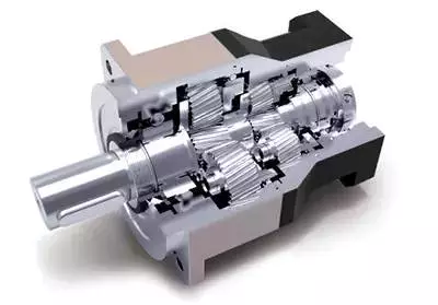
CZPT
The CZPT Planetary Gearbox is the perfect combination of compact size and high efficiency in power transmission. The compact design allows this gearbox to run silently while still delivering high power density and transmission efficiency. The CZPT Planetary Gearbox has several advantages. Unlike conventional planetary gearboxes, CZPT’s planetary gearbox features high power density, low torque, and optimum transmission efficiency.
CZPT’s products have been used in a variety of applications for many years, proving their reliability and quality. These products are renowned in the world for their reliability and quality. CZPT’s planetary gearboxes are backed by a five-year warranty. These features help customers choose a planetary gearbox that meets their needs and stays in top shape for years to come. But how do you test a planetary gearbox?
Figure 17 shows the response of a planetary gearbox to vibration. The maximum displacement in xg direction at a 50% crack level is shown by the dashed line. The signal in xg direction is called the xsignal. Moreover, the CZPT Planetary Gearbox’s vibration response is highly sensitive to the location of the bearings. For this reason, dynamic modeling of a planetary gearbox should consider bearing clearance.
CZPT’s hollow cup motor drive system features high reliability and low power consumption. The gearbox is compatible with industries with high quality standards, as there is no cogging torque. Its compact size and low electromagnetic noise make it ideal for a variety of applications. For industries with high product quality requirements, the CZPT Hollow Cup Motor Drive System is an excellent choice. It is also designed for vertical installation. You can even buy multiple CZPT products to meet your specific needs.
CZPT
With its PL series planetary gearboxes, CZPT has expanded its product portfolio to include more types of drive solutions. CZPT is one of the few companies to have won the Schneider Electric Supplier Award for Quality. In addition, its high-quality planetary gearboxes are highly customizable, allowing designers to customize each gearbox for the application at hand. Whether it is a geared pump or a stepper motor, CZPT’s PLE planetary gearboxes are built to meet the exact specifications of the application at hand.
The flange-mounted version of the planetary gearbox is comparable to its planetary counterpart. Using a flange-mounted planetary gearbox allows for a smaller, more compact design. This model also features a large-diameter output shaft, which helps achieve a higher level of torsional stiffness. This makes CZPT flange gearboxes particularly useful for applications where the direction of motion can change frequently. These gearboxes can be used with a wide variety of belts.
The PLQE 60-mm gearbox is used in Outrider’s single-stage design. Its gear ratio is 5:1, while its dual-stage version has a 15:1 gear ratio. Both gearboxes have identical mounting configurations, but the two-stage version is slightly longer.
The PLN series of planetary gearheads from CZPT are the standard for high-precision applications. They’re compatible with all major motor brands and sizes, and the company’s adapter kits are available to fit almost any motor. This makes CZPT gearheads one of the easiest to integrate into a complex machine. They’re also extremely easy to install, with the same torque as their corresponding spur gears.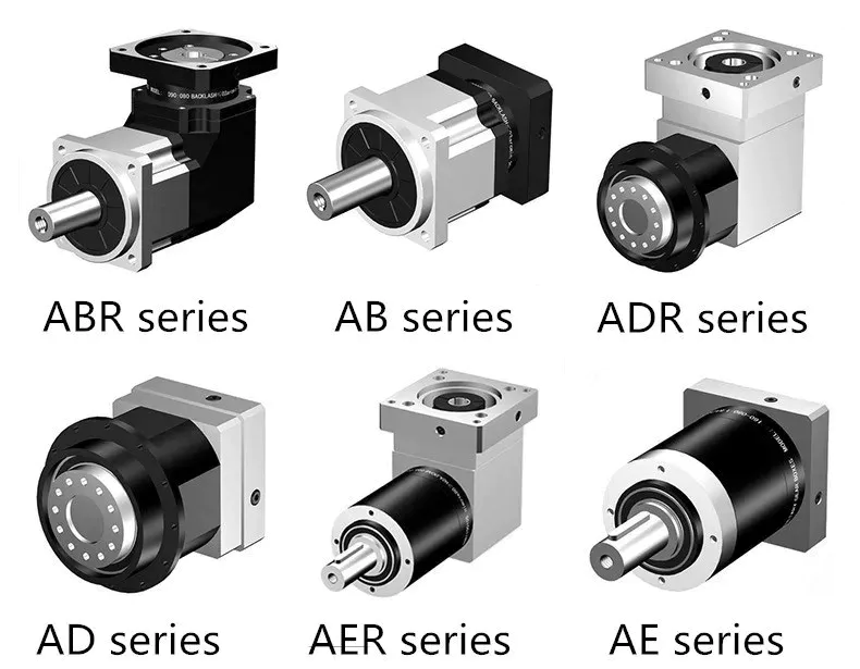
CZPT’s
If you are looking for an efficient solution for screw press applications, consider using CZPT’s 300M Planetary Gearbox. It has high axial and radial load capacities, compact design, high torque output, and torque arm. The 300M planetary gearbox is compatible with a variety of screw presses, including hydraulic press systems and digester systems. Its Torque control and direct coupling feature makes it easy to install.
CZPT’s small planetary gearboxes have an output torque of 20:1 from individual ratios of 5:1 and 4:1. They run silently and deliver maximum transmission efficiency. The planetary gears are mounted on a ring that is fixed around the center sun gear. The ring acts as an output torque converter for the next planet stage. This planetary gearbox has multiple stages and a maximum ratio of 20:1 can be created from individual ratios of 5:1 and 4:1.
CZPT Motor is an innovator in the design and manufacture of miniature motors for industrial robots. Its offerings include brushless DC and brushed DC motors, as well as planetary gearboxes, encoders, and brakes. CZPT’s products have a variety of uses in robotics, intelligent appliances, medical equipment, communication, and industrial automation. The company is also committed to providing custom designs based on customer specifications.
Another advantage of a planetary gearbox is its high power transmission efficiency. It is capable of approximately 3% per stage, allowing it to transmit more torque than a conventional single-stage gearbox. Planetary gearboxes are also compact and have a high torque-to-weight ratio. CZPT’s Planetary Gearbox is the best choice for many applications. This gearbox offers the highest efficiency and is ideal for small-scale production.


editor by CX 2023-10-18
China High Precision Low Backlash Ratio 50: 1 Spur Planetary Gear Box with Best Sales
Product Description
High Precision Minimal Backlash Ratio 50:1 Spur Planetary Gear Box
Planetary gearbox is a variety of reducer with extensive flexibility. The inner equipment adopts reduced carbon alloy steel carburizing quenching and grinding or nitriding method. Planetary gearbox has the qualities of little construction size, massive output torque, substantial speed ratio, large effectiveness, protected and reliable overall performance, and so on. The inner gear of the planetary gearbox can be divided into spur equipment and helical gear. Buyers can decide on the appropriate precision reducer according to the requirements of the software.
Product Parameters
Characteristics:
one.Output threaded connection, common set up,common use
two.Single cantilever structure.basic style,economic price tag
3.Operating continual. Low noise
four.Round flange output,threaded reverse relationship,standardized dimensions
5.Keyway can be opened in the power shaft
six.The output connection technical specs are full and there are many choices
7.Minimal backlash. Can go well with most occasion
eight.Pace ratio range:3-100
9.Precision assortment:8-16arcmin
ten.Dimension selection:sixty-160mm.
| Specifications | PRN60 | PRN80 | PRN90 | PRN120 | PRN160 | |||
| Technal Parameters | ||||||||
| Max. Torque | Nm | 1.5times rated torque | ||||||
| Emergency End Torque | Nm | 2.5times rated torque | ||||||
| Max. Radial Load | N | 240 | four hundred | 450 | 1240 | 2250 | ||
| Max. Axial Load | N | 220 | 420 | 430 | one thousand | 1500 | ||
| Torsional Rigidity | Nm/arcmin | one.eight | four.7 | four.eighty five | 11 | 35 | ||
| Max.Enter Speed | rpm | 8000 | 6000 | 6000 | 6000 | 4000 | ||
| Rated Input Pace | rpm | 4000 | 3500 | 3500 | 3500 | 3000 | ||
| Noise | dB | ≤58 | ≤60 | ≤60 | ≤65 | ≤70 | ||
| Average Existence Time | h | 20000 | ||||||
| Efficiency Of Total Load | % | L1≥96% L2≥94% | ||||||
| Return Backlash | P1 | L1 | arcmin | ≤8 | ≤8 | ≤8 | ≤8 | ≤8 |
| L2 | arcmin | ≤12 | ≤12 | ≤12 | ≤12 | ≤12 | ||
| P2 | L1 | arcmin | ≤16 | ≤16 | ≤16 | ≤16 | ≤16 | |
| L2 | arcmin | ≤20 | ≤20 | ≤20 | ≤20 | ≤20 | ||
| Moment Of Inertia Desk | L1 | three | Kg*cm2 | .forty six | .seventy seven | 1.73 | 12.78 | 36.72 |
| 4 | Kg*cm2 | .46 | .77 | 1.seventy three | twelve.seventy eight | 36.seventy two | ||
| 5 | Kg*cm2 | .forty six | .seventy seven | 1.seventy three | twelve.78 | 36.72 | ||
| 7 | Kg*cm2 | .forty one | .65 | one.42 | eleven.38 | 34.02 | ||
| 10 | Kg*cm2 | .41 | .65 | 1.forty two | 11.38 | 34.02 | ||
| L2 | twelve | Kg*cm2 | .forty four | .72 | 1.forty nine | twelve.18 | 34.24 | |
| 15 | Kg*cm2 | .44 | .seventy two | 1.forty nine | 12.18 | 34.24 | ||
| 16 | Kg*cm2 | .seventy two | .72 | one.49 | twelve.18 | 34.24 | ||
| twenty | Kg*cm2 | .44 | .seventy two | 1.49 | twelve.18 | 34.24 | ||
| 25 | Kg*cm2 | .forty four | .72 | 1.forty nine | 12.18 | 34.24 | ||
| 28 | Kg*cm2 | .44 | .72 | 1.49 | 12.eighteen | 34.24 | ||
| thirty | Kg*cm2 | .forty four | .72 | 1.forty nine | 12.18 | 34.24 | ||
| 35 | Kg*cm2 | .44 | .seventy two | one.forty nine | 12.18 | 34.24 | ||
| forty | Kg*cm2 | .forty four | .72 | 1.49 | 12.eighteen | 34.24 | ||
| fifty | Kg*cm2 | .34 | .58 | one.twenty five | eleven.forty eight | 34.02 | ||
| 70 | Kg*cm2 | .34 | .58 | 1.twenty five | eleven.forty eight | 34.02 | ||
| 100 | Kg*cm2 | .34 | .fifty eight | one.25 | eleven.forty eight | 34.02 | ||
| Specialized Parameter | Level | Ratio | PRN60 | PRN80 | PRN90 | PRN120 | PRN160 | |
| Rated Torque | L1 | three | Nm | 27 | 50 | ninety six | 161 | 364 |
| four | Nm | 40 | ninety | 122 | 210 | 423 | ||
| five | Nm | 40 | 90 | 122 | 210 | 423 | ||
| seven | Nm | 34 | forty eight | ninety five | a hundred and seventy | 358 | ||
| 10 | Nm | 16 | 22 | 56 | 86 | 210 | ||
| L2 | 12 | Nm | 27 | 50 | ninety six | 161 | 364 | |
| 15 | Nm | 27 | 50 | 96 | 161 | 364 | ||
| 16 | Nm | forty | ninety | 122 | 210 | 423 | ||
| twenty | Nm | 40 | 90 | 122 | 210 | 423 | ||
| 25 | Nm | forty | ninety | 122 | 210 | 423 | ||
| 28 | Nm | forty | 90 | 122 | 210 | 423 | ||
| 30 | Nm | 27 | fifty | ninety six | 161 | 364 | ||
| 35 | Nm | forty | 90 | 122 | 210 | 423 | ||
| 40 | Nm | 40 | ninety | 122 | 210 | 423 | ||
| fifty | Nm | 40 | 90 | 122 | 210 | 423 | ||
| 70 | Nm | 34 | forty eight | 95 | a hundred and seventy | 358 | ||
| 100 | Nm | 16 | 22 | fifty six | 86 | 210 | ||
| Degree Of Defense | IP65 | |||||||
| Operation Temprature | ºC | – 10ºC to -90ºC | ||||||
| Weight | L1 | kg | .95 | 2.27 | three.06 | six.93 | fifteen.5 | |
| L2 | kg | one.two | two.8 | 3.86 | eight.ninety eight | seventeen | ||
Business Profile
Packaging & Transport
| Application: | Motor, Motorcycle, Machinery, Marine, Agricultural Machinery, Manipulator |
|---|---|
| Function: | Change Drive Torque, Change Drive Direction, Speed Reduction |
| Layout: | Coaxial |
| Hardness: | Hardened Tooth Surface |
| Installation: | Vertical Type |
| Step: | Single-Step |
###
| Samples: |
US$ 305/Piece
1 Piece(Min.Order) |
|---|
###
| Customization: |
Available
|
|---|
###
| Specifications | PRN60 | PRN80 | PRN90 | PRN120 | PRN160 | |||
| Technal Parameters | ||||||||
| Max. Torque | Nm | 1.5times rated torque | ||||||
| Emergency Stop Torque | Nm | 2.5times rated torque | ||||||
| Max. Radial Load | N | 240 | 400 | 450 | 1240 | 2250 | ||
| Max. Axial Load | N | 220 | 420 | 430 | 1000 | 1500 | ||
| Torsional Rigidity | Nm/arcmin | 1.8 | 4.7 | 4.85 | 11 | 35 | ||
| Max.Input Speed | rpm | 8000 | 6000 | 6000 | 6000 | 4000 | ||
| Rated Input Speed | rpm | 4000 | 3500 | 3500 | 3500 | 3000 | ||
| Noise | dB | ≤58 | ≤60 | ≤60 | ≤65 | ≤70 | ||
| Average Life Time | h | 20000 | ||||||
| Efficiency Of Full Load | % | L1≥96% L2≥94% | ||||||
| Return Backlash | P1 | L1 | arcmin | ≤8 | ≤8 | ≤8 | ≤8 | ≤8 |
| L2 | arcmin | ≤12 | ≤12 | ≤12 | ≤12 | ≤12 | ||
| P2 | L1 | arcmin | ≤16 | ≤16 | ≤16 | ≤16 | ≤16 | |
| L2 | arcmin | ≤20 | ≤20 | ≤20 | ≤20 | ≤20 | ||
| Moment Of Inertia Table | L1 | 3 | Kg*cm2 | 0.46 | 0.77 | 1.73 | 12.78 | 36.72 |
| 4 | Kg*cm2 | 0.46 | 0.77 | 1.73 | 12.78 | 36.72 | ||
| 5 | Kg*cm2 | 0.46 | 0.77 | 1.73 | 12.78 | 36.72 | ||
| 7 | Kg*cm2 | 0.41 | 0.65 | 1.42 | 11.38 | 34.02 | ||
| 10 | Kg*cm2 | 0.41 | 0.65 | 1.42 | 11.38 | 34.02 | ||
| L2 | 12 | Kg*cm2 | 0.44 | 0.72 | 1.49 | 12.18 | 34.24 | |
| 15 | Kg*cm2 | 0.44 | 0.72 | 1.49 | 12.18 | 34.24 | ||
| 16 | Kg*cm2 | 0.72 | 0.72 | 1.49 | 12.18 | 34.24 | ||
| 20 | Kg*cm2 | 0.44 | 0.72 | 1.49 | 12.18 | 34.24 | ||
| 25 | Kg*cm2 | 0.44 | 0.72 | 1.49 | 12.18 | 34.24 | ||
| 28 | Kg*cm2 | 0.44 | 0.72 | 1.49 | 12.18 | 34.24 | ||
| 30 | Kg*cm2 | 0.44 | 0.72 | 1.49 | 12.18 | 34.24 | ||
| 35 | Kg*cm2 | 0.44 | 0.72 | 1.49 | 12.18 | 34.24 | ||
| 40 | Kg*cm2 | 0.44 | 0.72 | 1.49 | 12.18 | 34.24 | ||
| 50 | Kg*cm2 | 0.34 | 0.58 | 1.25 | 11.48 | 34.02 | ||
| 70 | Kg*cm2 | 0.34 | 0.58 | 1.25 | 11.48 | 34.02 | ||
| 100 | Kg*cm2 | 0.34 | 0.58 | 1.25 | 11.48 | 34.02 | ||
| Technical Parameter | Level | Ratio | PRN60 | PRN80 | PRN90 | PRN120 | PRN160 | |
| Rated Torque | L1 | 3 | Nm | 27 | 50 | 96 | 161 | 364 |
| 4 | Nm | 40 | 90 | 122 | 210 | 423 | ||
| 5 | Nm | 40 | 90 | 122 | 210 | 423 | ||
| 7 | Nm | 34 | 48 | 95 | 170 | 358 | ||
| 10 | Nm | 16 | 22 | 56 | 86 | 210 | ||
| L2 | 12 | Nm | 27 | 50 | 96 | 161 | 364 | |
| 15 | Nm | 27 | 50 | 96 | 161 | 364 | ||
| 16 | Nm | 40 | 90 | 122 | 210 | 423 | ||
| 20 | Nm | 40 | 90 | 122 | 210 | 423 | ||
| 25 | Nm | 40 | 90 | 122 | 210 | 423 | ||
| 28 | Nm | 40 | 90 | 122 | 210 | 423 | ||
| 30 | Nm | 27 | 50 | 96 | 161 | 364 | ||
| 35 | Nm | 40 | 90 | 122 | 210 | 423 | ||
| 40 | Nm | 40 | 90 | 122 | 210 | 423 | ||
| 50 | Nm | 40 | 90 | 122 | 210 | 423 | ||
| 70 | Nm | 34 | 48 | 95 | 170 | 358 | ||
| 100 | Nm | 16 | 22 | 56 | 86 | 210 | ||
| Degree Of Protection | IP65 | |||||||
| Operation Temprature | ºC | – 10ºC to -90ºC | ||||||
| Weight | L1 | kg | 0.95 | 2.27 | 3.06 | 6.93 | 15.5 | |
| L2 | kg | 1.2 | 2.8 | 3.86 | 8.98 | 17 | ||
Planetary Gearbox Components
The basic components of a planetary gearset are an input, output, and stationary position. Different types of planetary gearboxes will have different output ratios and torques. A leading company for planetary gearbox design, CZPT, provides the necessary components. These components can vary in both male and female shafts and come with a variety of modular options. Here are a few things to consider about each component.
CFHK Series
The CFHK Series is a multistage planetary gearbox that contains multiple planetary gears. The multiple teeth of each planetary gear mesh simultaneously during operation to increase the transmittable torque. The gears are case hardened and ground, and the ratios of the planetary gears are integers. They were first functionally described by Leonardo da Vinci in 1490. Today, the CFHK Series is a favorite among automotive engineers and manufacturers.
The CH Series offers high accuracy with a compact design and case hardened, hypoid, and helical gearing. These gearboxes are also available in the CFXR series, with low backlash and friction. These planetary gearboxes are designed to provide high torque and high precision in a variety of applications. In addition, the CFXR series features 100% helical gearing and low backlash.
The CFHK Series features a sun gear that drives the next stage. These gears can be put in series or serially in the same housing. In some cases, the output shaft of the first stage becomes the input shaft of the second stage. In addition, ring gears are also used as structural parts of smaller gearboxes. An example of a planetary gearbox is the pencil sharpener mechanism. The pencil is placed on an axis that is set on a sun gear. The sun gear drives the next planet stage.
A planetary gear unit’s gear ratio is determined by the number of teeth in the sun gear and ring gear. The smaller the sun gear, the smaller the ratio between the sun gear and planet gears. The largest gear ratio in a planetary gear unit is 10:1. A higher number of teeth increases the transmission ratio. In order to maximize torque, the planetary gears must be rearranged. A smaller sun gear will have higher torque than a large ring gear.
CFX Series
The HPN Harmonic Planetary(r) Series planetary gearboxes offer a low-cost solution with high-performance and high-reliability. This modular design is easy to install and requires very little maintenance. Its planetary design and full complement of needle rollers allow for extended life and quiet operation. In addition, the HPN Harmonic Planetary(r) Series is available in a range of sizes.
The compact size and high-speed design of planetary gearboxes results in excellent heat dissipation. However, high-speed or sustained performance applications may require lubricants. A planetary gearbox will have smaller minimum steps to minimize noise and vibration. Planetary gears will give you the highest level of efficiency while minimizing noise. As a result, they can provide high-quality 3D prints.
A planetary gear train is composed of a ring gear and planet gears, each supported by a carrier. A ring gear is pink, while the sun gear is red. The sun gear and carrier rotate around each other at a 45-degree angle. This is also known as an epicyclic gear. Planetary gearboxes are often found in space-constrained applications. The CFX Series features a compact design and excellent performance.
The CFX Series features a robust design that is easy to install. Its compact size makes installation of planetary gearboxes easier and faster. They are available in three different configurations for continuous, intermittent, and counter-clockwise operation. The CFX Series offers the perfect solution for your accelerating needs. They’re a great solution for any automotive or industrial application. You can easily configure the CFX Series to meet your specific requirements.
CAP Series
The Candy Controls CAP Series is a new generation of compact, precision planetary gearboxes that combine high torques with low backlash and exceptional wear resistance. This rotary flange planetary gearbox is ideal for a variety of industrial, mining and marine applications. Its modular construction enables users to easily mount different stages, hydraulic or electric motors, and different types of gears. Its CPH Series features an extremely rigid alloy steel housing, carburized gears, and induction hardened gears.
The CAP Series utilizes multiple planetary gears for high torque transmission. The number of planetary gears is not fixed, but most planetary gearboxes utilize at least three. The larger the number of planetary gears, the higher the transmittable torque. A planetary gearbox is composed of multiple planetary gears with a meshing action that occurs simultaneously during operation. The result is a higher efficiency and a smoother, quieter operation than a conventional gearbox.
The VersaPlanetary range features modular design for easy installation. This system includes mounting plates for typical FIRST (r) Robotics Competition motors. The mounting plates are designed to fit each motor. These planetary gearboxes are compatible with various types of motors, from small electric motors to large, heavy duty ones. They are also compatible with a variety of mounting systems, including CIM motors.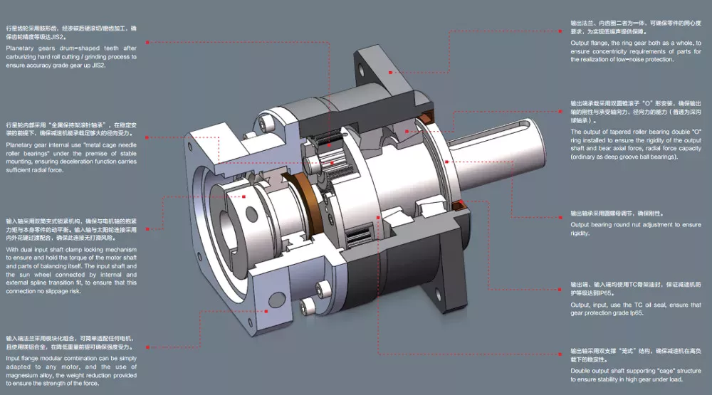
CAPK Series
The CZPT APK Series is a high precision, rotary flange style planetary gearbox. Its case hardened and ground gears are designed to provide excellent wear resistance, low backlash, and excellent precision. The CAPK Series offers high axial and moment load capacities in a compact housing. CZPT is the world leader in the production of planetary gearboxes. The CAPK Series features an array of high-quality, innovative features.
CZPT SMART Lubrication technology is used to keep the gears well-lubricated and reduce noise and vibration. The planetary gearbox’s 3-gear design is ideal for DIY CNC robotics. This series has a long history of quality, and CZPT uses only the best components. The CZPT 3:1 High Precision Planetary Gearbox is an excellent choice for CNC Robotics and other applications.
A multi-stage planetary gearbox combines individual ratios for a greater number of ratios. Additional planetary gears increase the transmittable torque. The direction of the output and drive shaft are always identical. The CAPK Series features a high-quality, durable construction. They are made from stainless steel and offer a long-term warranty. They are the best choice for industrial and commercial applications. While planetary gears are more expensive, they are highly efficient.
CFH Series
The Candy CFH Series planetary gearboxes offer the benefits of a modular design and a low backlash. They offer a variety of size options and excellent durability. This planetary gearbox is compact and wear resistant. The CFH Series planetary gearbox has a carburized, induction hardened gears and a rigid alloy steel housing. Its low backlash and precision make it an excellent choice for industrial applications.
The CFH Series planetary gearbox is a highly efficient, high-speed helical gear. The compact design of this gearbox results in high heat dissipation and low mass inertia. Planet carrier bearings experience significant lateral forces from the transmission of torque. As a result, radial and axial forces oppose each other. The result is that the torque is distributed over three gears, reducing noise, vibration, and wear.
The planetary gearbox has three main components: a sun gear (also known as the input gear), a ring gear, and two planet gears. These are connected by a carrier that rotates about a 45-degree clockwise axis. The CFH Series of gears is available in triple and double stages. They can also be used in electric motors. As a result, the CFH Series is highly versatile.
The CFH Series of planetary gearboxes can be found in all kinds of applications, including automotive transmissions. Their compact design and high-performance performance make them a popular choice for space-constrained applications. This gearbox has several benefits and is a great alternative to a conventional helical gearbox. These gearboxes are highly effective for reducing torque and speed, and are compact enough to fit in most applications.
CZPT
If you need a high-quality planetary gearbox, the CZPT Planetary Series is the right choice. This Italian company designs and manufactures gearboxes in its San Polo d’Enza, Italy, facility with 11 branch offices and three production facilities. The company is attempting to replicate the success of the Italian Super Car industry, which has gained global recognition. The company provides a range of gearboxes for use in heavy industry, agriculture, offshore, aerial and marine work.
With over 40 years of experience, CZPT manufactures a wide range of high-quality gearboxes. From bevel-helical units to Helical units, wheel gears and negative brakes, the company has been manufacturing quality components for many industries. CZPT is a trusted Australian distributor of CZPT gear components. The company is dedicated to providing the best planetary gears for every industry.
If your CZPT Planetary gearbox is malfunctioning, you can have it repaired quickly and easily. The company uses quality materials and a variety of sizes and output ratios to cater to the most demanding applications. In addition, you can customize your gearbox to suit your specific needs. CZPT Planetary Gearboxes are highly versatile and customizable, offering infinite scalability.
editor by czh 2023-01-28
China ZD Vertical Type Spur Helical Gear Planetary Reducer Gearbox For Automation Equipment supplier
Product Description
Product Choice
Planetar y gearbox is a variety of reducer with vast versatility. The inner equipment adopts lower carbon alloy metal carburizing quenching and grinding or nitriding method. Planetary gearbox has the traits of modest structure size, massive output torque, higher speed ratio, higher performance, risk-free and reliable efficiency, and many others. The interior gear of the planetary gearbox can be divided into spur gear and helical equipment.
• Model Choice
Our expert revenue representive and complex group will decide on the appropriate product and transmission options for your utilization count on your certain parameters.
• Drawing Ask for
If you require more product parameters, catalogues, CAD or 3D drawings, you should contact us.
• On Your Want
We can modify normal products or customise them to meet your particular requirements.
Selection Of Planetary Gearbox
Other Items
Business Profile
|
US $35-500 / Piece | |
1 Piece (Min. Order) |
###
| Application: | Motor, Machinery, Marine, Agricultural Machinery |
|---|---|
| Function: | Change Drive Torque, Speed Changing, Speed Reduction |
| Hardness: | Hardened Tooth Surface |
| Installation: | Vertical Type |
| Type: | Planetary Gear Box |
| Size: | 60mm-160mm |
###
| Samples: |
US$ 100/Piece
1 Piece(Min.Order) |
|---|
###
| Customization: |
Available
|
|---|
|
US $35-500 / Piece | |
1 Piece (Min. Order) |
###
| Application: | Motor, Machinery, Marine, Agricultural Machinery |
|---|---|
| Function: | Change Drive Torque, Speed Changing, Speed Reduction |
| Hardness: | Hardened Tooth Surface |
| Installation: | Vertical Type |
| Type: | Planetary Gear Box |
| Size: | 60mm-160mm |
###
| Samples: |
US$ 100/Piece
1 Piece(Min.Order) |
|---|
###
| Customization: |
Available
|
|---|
Benefits of a Planetary Gearbox With Output Shaft
The output shaft of a Planetary Gearbox connects to the driven wheels, while the input shaft comes from the engine. These gears are interlinked and create a wide range of gear reductions, which are necessary to get a vehicle rolling comfortably. Gear reductions are the place where the various “gears” are located. Here are some examples. They can help you determine what you need for your vehicle. You might also want to learn about planetary gears.
Planetary gearboxes
Modern cars are most likely equipped with planetary gearboxes. If you’re unsure if your vehicle uses planetary gears, you should first consult your car’s owner’s manual. If not, contact your dealership’s service department for more information. Otherwise, you can do a quick search on the internet to find out whether your car has a planetary gearbox. These gearboxes are generally more complex than ordinary gears. Additionally, they are equipped with more parts and require lubrication.
In addition to their low noise levels, planetary gearboxes are also remarkably efficient at transmission. These features make them ideal for applications requiring high torque and small footprints. Unfortunately, there are many different types of planetary gearboxes on the market, making it difficult to find the right one. The following article will give you some guidelines to help you choose the right planetary gearbox for your needs. Let’s take a look!
Planetary gears
A planetary gearbox has two main components: the sun gear (also known as the central or input) and the planet gears (also known as outer or peripheral). These gears are connected together by a carrier to the output shaft of the machine. In some applications, it is necessary to use a planetary gearbox with lubrication to prevent wear and tear. A planetary gearbox also has a small ring gear that helps hold the planet gears together.
The main advantage of a planetary gearbox is that it uses several teeth that engage at once, allowing for high-speed reduction with a small number of gears. Because the gears are relatively small, they have lower inertia than their larger counterparts. Planetary gearboxes are compact, which makes them popular for space-constrained applications. Because of their compact size and efficiency, planetary gearboxes are also commonly used in motor vehicles.
Planetary gearboxes with output shaft
For high-speed, dynamic applications, planetary gearbox units with output shaft provide the optimal solution. Thanks to their low inertia, these gearheads deliver superior performance in many industrial applications. Additionally, their wide range of variants allows users to select the perfect product for their application. This article examines some of the key benefits of planetary gearboxes with output shaft. Read on to learn more.
The planetary gearbox has two major components: a sun gear and planet gears. The sun gear is usually the input gear, while the planet gears are located at the outer edges of the system casing. Planet gears are held together by a carrier that is connected to the output shaft. Before choosing a particular gearbox for your application, make sure that you check the specific requirements and the environment to which the unit will be subjected.
A planetary gearbox has less stages of gears, and thus lower backlash compared to spur gearboxes. Backlash is lost motion that occurs when the teeth of the gears are out of perfect alignment. This problem is common in all gears, but is significantly less in planetary gearboxes. As such, planetary gearboxes are more efficient. They can also be customized according to the specific engine model and motor flange.
Planetary gearboxes with carrier
A planetary gearbox is a type of gearbox with three or more stages. They have a sun gear, which is usually the input gear, and planet gears, also called the outer gears. The carrier that connects the planet gears to the output shaft is called a ring gear. A planetary gearbox is generally designed to meet specific application and environmental requirements, but there are some factors to consider when choosing one.
The compact footprint of planetary gear sets results in high heat dissipation. This can be a problem in applications with sustained performance or high speeds. As a result, planetary gear sets often include lubricants, which present a cooling effect while also reducing noise and vibration. Some planetary gears even feature a carrier to make the installation process easier. Here are some things to keep in mind when choosing a planetary gear set.
Planetary gearboxes with carrier have several advantages over other types of gearboxes. Unlike conventional gearboxes, planetary gears have a common central shaft, and the tangential forces between the gears cancel out at the center of the ring gear. Because of this, planetary gearboxes are commonly used in input/output applications, and their compact size allows for a wide range of gear reductions. These gears can also produce higher torque density.
Planetary gearboxes with traction
Planetary gears are similar to the planetary system, in that each pinion rotates around a sun gear. The output of the planetary gear unit is lower than the drive rotation speed, but the torque is higher. As the number of planet gear wheels increases, so does the torque. Planetary gear systems contain three to four planet gears, and each is in constant mesh with the others. Power applied to any one member rotates the entire assembly.
Typical applications for planetary gear sets include high-precision motion control. In these applications, high torque, torsional stiffness, and low backlash are required. Planetary gear sets are also ideal for motors with higher speeds. A number of factors contribute to the reliability of these devices. The low backlash and large torque capacity of a planetary gear motor allow them to be used in a wide range of applications.
Planetary gearboxes with electric motors
If you’re in the market for a new gearbox, you may have already heard about planetary gearboxes. The planetary gearbox is a high-efficiency, low-noise gearbox. CZPT manufactures high-torque planetary gearboxes with low backlash. They also make economy planetary gearboxes for lower loads. However, with so many different types available, choosing the right one for your needs can be challenging.
These planetary gearboxes are a compact alternative to conventional pinion-and-gear reducers. They offer high-speed reduction and high torque transfer, and are often used for space-constrained applications. But before you can understand how they work, you’ll need to understand a little about their construction. There are a few things to look for that you may not have noticed before.
The most common type of planetary gearbox is a PM81/LN. It features a set of DC brush motors with diameter 77mm, a stator, and two or more outer gears. Each of these gears is connected to an output shaft through a carrier. They can also be used with brakes, encoders, or a clutch. A planetary gearbox is one of the most reliable gearbox types on the market.
Planetary gearboxes with hydraulic motors
A planetary gearbox is a combination of two gears, the sun and the planets. The sun gear rotates at high speed, while the planets roll around and orbit around the ring gear. The output shaft has the same direction of rotation as the input shaft. The benefits of a planetary gearbox include high reduction ratios, efficiency, space-saving compactness, and higher overload capacity. These gears are also more stable and compact, and they do not suffer from self-locking properties.
Planetary gearboxes are a highly efficient way to power hydraulic lifts. They can be input via electric, hydraulic, or air motors. The drive arrangement can be mounted on a bare shaft, splined shaft, or a parallel keyed input shaft. Depending on the application, bespoke gearboxes can be manufactured with a variety of features and functions.
Planetary gearboxes with combustion engines
There are many different applications of planetary gear sets. The most common is the distribution of power between two wheels in a car’s drive axle. Four-wheel drives use two axle differentials, which are further augmented by a centre differential. Hybrid electric vehicles use summation gearboxes to distribute power from the combustion engine to the wheels and to an electric motor. Planetary gear sets also combine the two different types of motors to form one hybrid vehicle.
To understand how planetary gear sets work, it is important to understand the underlying mechanical principles. For example, Fig. 4.6 shows a stick diagram illustrating two planetary gear sets connected by a lever. The two levers are the same length, so the system is analogous to a single lever. When calculating the torque, it is essential to consider the lever diagram. Similarly, if two gear sets are connected by vertical links, the horizontal links must be horizontal.
editor by czh 2023-01-03
China Good quality Forging Steel Metal Spur Kiln Pinion Large Module Gear Wheel near me factory
Product Description
Solution Description
Major Positive aspects
one) Powder metallurgy can make sure the precision and uniformity of the substance composition ratio.
two) Appropriate for generating products of the identical condition and large quantities, reduced manufacturing value.
three) The manufacturing process is not concerned of oxidation, and no substance air pollution will arise.
four) No subsequent machining processing is essential, saving supplies and lowering expenses.
five) Most difficult metals and compounds, pseudo alloys, porous components can only be made by powder metallurgy
FAQ
Q: Are you trading organization or manufacturer ?
A: We are factory and trading business
Q: How long is your shipping time?
A: Typically it is 5-ten days if the items are in stock. or it is 15-20 days if the products are not in stock, it is according to amount.
Q: Do you offer samples ? is it cost-free or extra ?
A: Sure, we could provide the sample for free of charge cost but do not spend the cost of freight.
Q: What is your phrases of payment ?
A: Payment=1000USD, 30% T/T in CZPT ,balance prior to shippment.
If you have yet another question, pls feel cost-free to make contact with us as underneath:
Spiral Gears for Correct-Angle Right-Hand Drives
Spiral gears are utilised in mechanical techniques to transmit torque. The bevel gear is a certain sort of spiral gear. It is produced up of two gears that mesh with 1 an additional. Equally gears are linked by a bearing. The two gears should be in mesh alignment so that the damaging thrust will thrust them together. If axial play happens in the bearing, the mesh will have no backlash. Furthermore, the style of the spiral gear is based on geometrical tooth types.
Equations for spiral equipment
The principle of divergence needs that the pitch cone radii of the pinion and equipment be skewed in different instructions. This is completed by growing the slope of the convex area of the gear’s tooth and reducing the slope of the concave floor of the pinion’s tooth. The pinion is a ring-formed wheel with a central bore and a plurality of transverse axes that are offset from the axis of the spiral teeth.
Spiral bevel gears have a helical tooth flank. The spiral is constant with the cutter curve. The spiral angle b is equivalent to the pitch cone’s genatrix factor. The imply spiral angle bm is the angle among the genatrix component and the tooth flank. The equations in Table 2 are certain for the Distribute Blade and Solitary Side gears from Gleason.
The tooth flank equation of a logarithmic spiral bevel gear is derived utilizing the formation system of the tooth flanks. The tangential make contact with power and the typical strain angle of the logarithmic spiral bevel gear have been discovered to be about twenty levels and 35 degrees respectively. These two kinds of movement equations were utilised to fix the problems that crop up in determining the transmission stationary. Even though the concept of logarithmic spiral bevel gear meshing is nonetheless in its infancy, it does offer a good beginning point for comprehension how it operates.
This geometry has a lot of various answers. Even so, the main two are described by the root angle of the equipment and pinion and the diameter of the spiral equipment. The latter is a tough a single to constrain. A 3D sketch of a bevel equipment tooth is utilised as a reference. The radii of the tooth room profile are defined by conclude level constraints put on the base corners of the tooth space. Then, the radii of the gear tooth are determined by the angle.
The cone length Am of a spiral equipment is also identified as the tooth geometry. The cone length need to correlate with the numerous sections of the cutter path. The cone length variety Am have to be in a position to correlate with the strain angle of the flanks. The foundation radii of a bevel equipment need to have not be outlined, but this geometry must be regarded if the bevel gear does not have a hypoid offset. When establishing the tooth geometry of a spiral bevel gear, the first action is to transform the terminology to pinion as an alternative of gear.
The standard technique is far more hassle-free for producing helical gears. In addition, the helical gears have to be the identical helix angle. The opposite hand helical gears need to mesh with every single other. Likewise, the profile-shifted screw gears require much more complicated meshing. This equipment pair can be produced in a equivalent way to a spur gear. Even more, the calculations for the meshing of helical gears are presented in Desk 7-1.
Design of spiral bevel gears
A proposed layout of spiral bevel gears makes use of a operate-to-kind mapping method to figure out the tooth area geometry. This reliable product is then analyzed with a surface area deviation strategy to figure out regardless of whether it is precise. In comparison to other proper-angle gear kinds, spiral bevel gears are more productive and compact. CZPT Gear Business gears comply with AGMA requirements. A increased quality spiral bevel gear established achieves 99% efficiency.
A geometric meshing pair based mostly on geometric factors is proposed and analyzed for spiral bevel gears. This strategy can offer substantial get in touch with strength and is insensitive to shaft angle misalignment. Geometric aspects of spiral bevel gears are modeled and talked about. Make contact with patterns are investigated, as nicely as the influence of misalignment on the load capability. In addition, a prototype of the style is fabricated and rolling assessments are executed to validate its accuracy.
The three basic components of a spiral bevel equipment are the pinion-gear pair, the input and output shafts, and the auxiliary flank. The input and output shafts are in torsion, the pinion-equipment pair is in torsional rigidity, and the technique elasticity is tiny. These aspects make spiral bevel gears ideal for meshing impact. To improve meshing impact, a mathematical model is developed employing the tool parameters and original device settings.
In recent several years, several improvements in production technology have been made to create high-overall performance spiral bevel gears. Researchers such as Ding et al. optimized the device options and cutter blade profiles to get rid of tooth edge make contact with, and the outcome was an accurate and huge spiral bevel equipment. In reality, this process is still utilized today for the production of spiral bevel gears. If you are fascinated in this technology, you need to study on!
The layout of spiral bevel gears is complicated and intricate, necessitating the capabilities of expert machinists. Spiral bevel gears are the point out of the art for transferring electricity from 1 technique to one more. Even though spiral bevel gears have been after hard to manufacture, they are now typical and widely utilised in many apps. In simple fact, spiral bevel gears are the gold regular for correct-angle electricity transfer.Whilst standard bevel equipment machinery can be utilized to manufacture spiral bevel gears, it is extremely complicated to create double bevel gears. The double spiral bevel gearset is not machinable with conventional bevel gear machinery. For that reason, novel producing techniques have been designed. An additive producing strategy was employed to develop a prototype for a double spiral bevel gearset, and the manufacture of a multi-axis CNC device center will comply with.
Spiral bevel gears are critical parts of helicopters and aerospace power crops. Their longevity, stamina, and meshing functionality are vital for safety. A lot of scientists have turned to spiral bevel gears to handle these issues. One particular problem is to reduce sounds, increase the transmission effectiveness, and improve their endurance. For this purpose, spiral bevel gears can be scaled-down in diameter than straight bevel gears. If you are fascinated in spiral bevel gears, examine out this article.
Constraints to geometrically attained tooth types
The geometrically acquired tooth forms of a spiral equipment can be calculated from a nonlinear programming dilemma. The tooth technique Z is the linear displacement error alongside the contact regular. It can be calculated making use of the formula offered in Eq. (23) with a number of added parameters. Even so, the end result is not exact for tiny masses simply because the signal-to-sounds ratio of the pressure sign is modest.
Geometrically obtained tooth varieties can direct to line and position contact tooth types. Even so, they have their limits when the tooth bodies invade the geometrically obtained tooth form. This is referred to as interference of tooth profiles. Even though this restrict can be conquer by numerous other methods, the geometrically attained tooth varieties are limited by the mesh and energy of the enamel. They can only be used when the meshing of the equipment is adequate and the relative movement is enough.
For the duration of the tooth profile measurement, the relative place in between the gear and the LTS will constantly change. The sensor mounting surface area must be parallel to the rotational axis. The true orientation of the sensor could differ from this best. This could be because of to geometrical tolerances of the equipment shaft assist and the platform. Nonetheless, this result is minimum and is not a significant issue. So, it is achievable to receive the geometrically received tooth types of spiral gear with out going through pricey experimental processes.
The measurement procedure of geometrically acquired tooth varieties of a spiral equipment is based on an excellent involute profile produced from the optical measurements of one end of the equipment. This profile is assumed to be practically ideal based mostly on the basic orientation of the LTS and the rotation axis. There are modest deviations in the pitch and yaw angles. Reduce and upper bounds are identified as – 10 and -ten levels respectively.
The tooth types of a spiral equipment are derived from alternative spur toothing. Nonetheless, the tooth condition of a spiral gear is nonetheless subject matter to various constraints. In addition to the tooth condition, the pitch diameter also impacts the angular backlash. The values of these two parameters vary for every gear in a mesh. They are relevant by the transmission ratio. After this is comprehended, it is feasible to generate a equipment with a corresponding tooth shape.
As the duration and transverse base pitch of a spiral gear are the exact same, the helix angle of every single profile is equivalent. This is vital for engagement. An imperfect base pitch outcomes in an uneven load sharing among the gear enamel, which qualified prospects to increased than nominal loads in some tooth. This sales opportunities to amplitude modulated vibrations and sound. In addition, the boundary level of the root fillet and involute could be diminished or eradicate make contact with prior to the tip diameter.


China best CZPT Manufacture Small Nylon Plastic Transmission Parts Planetary Spur Gear for CNC Machinery Parts with Best Sales
Solution Description
IHF Manufacture Tiny Nylon Plastic Transmission Areas Planetary Spur Gear For CNC Equipment Elements
Major Characteristics:
Helical Gear
one. Make strictly in accordance with ANSI or DIN regular dimension
two. Material: 1045 Carbon Metal
three. Bore: Finished bore
four. Module: 1~three
Merchandise Parameters
Specifction:
Pulley Manufacturing Workshop and Software:
Machining Method
Associated Items
Firm Profile
HangZhou CZPT Machinery Co.,LTD set up in 2009, is a professional manufacture engaged in development, manufacturing, sales and support of timing pulley, precise spur gears, helical gears, bevel gear, worm& worm equipment and so on. We located in HangZhou with hassle-free transposition excite. CZPT Equipment focused to stringent good quality manage and thoughtful buyer service. Our seasoned staffs are constantly available to go over your demands, and satisfy your satisfaction.
Hefa Equipment Equipment focused to rigid quality manage.” Focus and Skilled on the Growth of Conveyor Area” this is CZPT Equipment focus on. Operate stage by step, CZPT often supply success remedy in precise conveyor discipline. Providing best value, tremendous support and typical delivery are usually our priorities.
Packaging & Shipping and delivery
FAQ
If you are interested in our merchandise, remember to inform us which supplies, variety, width, length u want.
Sorts of Bevel Gears
Bevel Gears are employed in a amount of industries. They are utilized in wheeled excavators, dredges, conveyor belts, mill actuators, and rail transmissions. A bevel gear’s spiral or angled bevel can make it suitable for confined areas. It is also utilized in robotics and vertical supports of rolling mills. You can use bevel gears in food processing processes. For a lot more info on bevel gears, go through on.
Spiral bevel gear
Spiral bevel gears are utilised to transmit power between two shafts in a 90-degree orientation. They have curved or oblique tooth and can be fabricated from numerous metals. Bestagear is a single manufacturer specializing in medium to large spiral bevel gears. They are used in the mining, metallurgical, maritime, and oil fields. Spiral bevel gears are generally made from metal, aluminum, or phenolic supplies.
Spiral bevel gears have numerous rewards. Their mesh enamel generate a significantly less abrupt power transfer. They are exceptionally tough and are made to final a lengthy time. They are also much less costly than other correct-angle gears. They also tend to last more time, because they are produced in pairs. The spiral bevel gear also reduces sounds and vibration from its counterparts. For that reason, if you are in need to have of a new gear established, spiral bevel gears are the appropriate selection.
The contact in between spiral bevel gear teeth takes place alongside the floor of the gear tooth. The make contact with follows the Hertz principle of elastic make contact with. This theory retains for little important dimensions of the contact area and small relative radii of curvature of the surfaces. In this scenario, strains and friction are negligible. A spiral bevel equipment is a typical case in point of an inverted helical equipment. This gear is typically used in mining gear.
Spiral bevel gears also have a backlash-absorbing function. This attribute will help secure the thickness of the oil film on the equipment surface area. The shaft axis, mounting distance, and angle problems all affect the tooth make contact with on a spiral bevel gear. Altering backlash will help to right these troubles. The tolerances proven over are typical for bevel gears. In some instances, manufacturers make slight design adjustments late in the manufacturing method, which minimizes the danger to OEMs.
Straight bevel equipment
Straight bevel gears are amid the easiest varieties of gears to manufacture. The earliest strategy utilized to manufacture straight bevel gears was to use a planer outfitted with an indexing head. However, improvements have been made in manufacturing strategies right after the introduction of the Revacycle program and the Coniflex. The most recent technological innovation makes it possible for for even more precise production. The two of these producing techniques are used by CZPT. Below are some illustrations of straight bevel equipment manufacturing.
A straight bevel equipment is made using two kinds of bevel surfaces, namely, the Gleason approach and the Klingelnberg method. Amongst the two, the Gleason technique is the most frequent. As opposed to other types of gear, the CZPT approach is not a universal normal. The Gleason system has greater top quality gears, given that its adoption of tooth crowning is the most powerful way to make gears that tolerate even small assembly glitches. It also eliminates the anxiety concentration in the bevelled edges of the tooth.
The gear’s composition is dependent on the software. When toughness is necessary, a equipment is created of solid iron. The pinion is typically three moments more difficult than the gear, which assists harmony use. Other supplies, this sort of as carbon steel, are cheaper, but are much less resistant to corrosion. Inertia is an additional critical issue to consider, because heavier gears are more difficult to reverse and quit. Precision demands may contain the equipment pitch and diameter, as effectively as the strain angle.
Involute geometry of a straight bevel gear is usually computed by various the surface’s standard to the surface area. Involute geometry is computed by incorporating the area coordinates and the theoretical tooth thickness. Utilizing the CMM, the spherical involute floor can be utilised to decide tooth get in touch with designs. This approach is valuable when a roll tester tooling is unavailable, due to the fact it can predict the teeth’ get in touch with sample.
Hypoid bevel equipment
Hypoid bevel gears are an effective and flexible velocity reduction resolution. Their compact size, large efficiency, lower sound and warmth era, and long existence make them a well-known decision in the electrical power transmission and movement manage industries. The following are some of the rewards of hypoid gearing and why you need to use it. Detailed below are some of the important misperceptions and untrue assumptions of this equipment type. These assumptions might appear counterintuitive at first, but will help you comprehend what this gear is all about.
The fundamental concept of hypoid gears is that they use two non-intersecting shafts. The smaller equipment shaft is offset from the greater equipment shaft, making it possible for them to mesh without interference and assist every other securely. The ensuing torque transfer is improved when compared to conventional equipment sets. A hypoid bevel gear is used to generate the rear axle of an automobile. It raises the overall flexibility of machine layout and makes it possible for the axes to be freely altered.
In the initial case, the mesh of the two bodies is obtained by fitting the hyperboloidal cutter to the preferred gear. Its geometric qualities, orientation, and place decide the wanted equipment. The latter is employed if the preferred equipment is sound-cost-free or is needed to minimize vibrations. A hyperboloidal cutter, on the other hand, meshes with two toothed bodies. It is the most productive selection for modeling hypoid gears with sound issues.
The primary distinction between hypoid and spiral bevel gears is that the hypoid bevel equipment has a greater diameter than its counterparts. They are usually found in 1:1 and 2:1 applications, but some makers also provide higher ratios. A hypoid gearbox can attain speeds of three thousand rpm. This tends to make it the chosen decision in a range of applications. So, if you are hunting for a gearbox with a large effectiveness, this is the equipment for you.
Addendum and dedendum angles
The addendum and dedendum angles of a bevel gear are used to describe the form and depth of the enamel of the gear. Each tooth of the equipment has a a bit tapered surface area that changes in depth. These angles are described by their addendum and dedendum distances. Addendum angle is the distance among the best land and the bottom surface of the enamel, although dedendum angle is the length among the pitch surface and the bottom area of the enamel.
The pitch angle is the angle shaped by the apex position of the gear’s pitch cone with the pitch line of the equipment shaft. The dedendum angle, on the other hand, is the depth of the tooth area beneath the pitch line. Equally angles are employed to measure the condition of a bevel gear. The addendum and dedendum angles are important for gear design.
The dedendum and addendum angles of a bevel gear are determined by the foundation speak to ratio (Mc) of the two gears. The involute curve is not authorized to extend within the foundation diameter of the bevel gear. The base diameter is also a essential measurement for the style of a gear. It is feasible to decrease the involute curve to match the involute curve, but it need to be tangential to the involute curve.
The most typical application of a bevel equipment is the automotive differential. They are utilised in a lot of types of cars, such as autos, trucks, and even building tools. They are also utilised in the maritime business and aviation. Apart from these two typical employs, there are several other uses for bevel gears. And they are nonetheless developing in acceptance. But they are a worthwhile portion of automotive and industrial gearing methods.
Programs of bevel gears
Bevel gears are employed in a selection of applications. They are manufactured of different materials depending on their weight, load, and software. For substantial-load purposes, ferrous metals this kind of as gray cast iron are utilized. These materials have superb put on resistance and are affordable. For reduce-fat applications, metal or non-metals this kind of as plastics are used. Some bevel equipment materials are considered noiseless. Right here are some of their most typical uses.
Straight bevel gears are the least difficult to manufacture. The earliest approach of manufacturing them was with a planer with an indexing head. Modern production methods launched the Revacycle and Coniflex techniques. For industrial gear production, the CZPT utilizes the Revacycle program. Even so, there are many sorts of bevel gears. This information will help you select the appropriate material for your up coming task. These supplies can withstand large rotational speeds and are really powerful.
Bevel gears are most frequent in automotive and industrial equipment. They hook up the driveshaft to the wheels. Some even have a 45-degree bevel. These gears can be positioned on a bevel surface and be examined for their transmission abilities. They are also utilised in tests applications to make sure proper motion transmission. They can lessen the velocity of straight shafts. Bevel gears can be utilized in many industries, from maritime to aviation.
The most basic variety of bevel equipment is the miter gear, which has a 1:1 ratio. It is utilized to alter the axis of rotation. The shafts of angular miter bevel gears can intersect at any angle, from forty five levels to one hundred twenty degrees. The tooth on the bevel gear can be straight, spiral, or Zerol. And as with the rack and pinion gears, there are different kinds of bevel gears.
China best CZPT Processing Customized Helical Gears Double Transmission Spur Bevel Gear for Metal machinery Part with Good quality
Solution Description
CZPT Processing Customized Helical Gears Double Transmission Spur Bevel Equipment For Metal Machiney Component
Major Characteristics:
Helical Equipment
1. Make strictly in accordance with ANSI or DIN common dimension
two. Substance: 1045 Carbon Steel
3. Bore: Finished bore
four. Module: 1~three
Merchandise Parameters
Specifction:
Machining Method
Relevant Products
Firm Profile
HangZhou CZPT Equipment Co.,LTD proven in 2009, is a professional manufacture engaged in growth, generation, sales and provider of timing pulley, specific spur gears, helical gears, bevel gear, worm& worm equipment and so on. We positioned in HangZhou with convenient transposition excite. CZPT Equipment committed to stringent top quality control and thoughtful customer support. Our knowledgeable staffs are usually obtainable to talk about your needs, and fulfill your pleasure.
Hefa Gear Machinery focused to stringent quality manage.” Focus and Specialist on the Growth of Conveyor Field” this is CZPT Equipment focus on. Perform stage by action, CZPT constantly provide accomplishment remedy in specific conveyor area. Giving very best price, tremendous service and regular delivery are often our priorities.
Packaging & Delivery
FAQ
If you are fascinated in our goods, please explain to us which materials, sort, width, length u want.
Spiral Gears for Appropriate-Angle Appropriate-Hand Drives
Spiral gears are utilised in mechanical systems to transmit torque. The bevel gear is a specific sort of spiral equipment. It is made up of two gears that mesh with a single one more. Each gears are linked by a bearing. The two gears have to be in mesh alignment so that the damaging thrust will press them jointly. If axial enjoy takes place in the bearing, the mesh will have no backlash. Moreover, the design and style of the spiral equipment is dependent on geometrical tooth varieties.
Equations for spiral equipment
The theory of divergence demands that the pitch cone radii of the pinion and equipment be skewed in various instructions. This is completed by growing the slope of the convex area of the gear’s tooth and decreasing the slope of the concave surface area of the pinion’s tooth. The pinion is a ring-formed wheel with a central bore and a plurality of transverse axes that are offset from the axis of the spiral tooth.
Spiral bevel gears have a helical tooth flank. The spiral is constant with the cutter curve. The spiral angle b is equal to the pitch cone’s genatrix factor. The indicate spiral angle bm is the angle among the genatrix element and the tooth flank. The equations in Desk 2 are certain for the Spread Blade and Solitary Aspect gears from Gleason.
The tooth flank equation of a logarithmic spiral bevel gear is derived making use of the formation mechanism of the tooth flanks. The tangential speak to drive and the regular force angle of the logarithmic spiral bevel gear had been discovered to be about twenty degrees and 35 degrees respectively. These two varieties of movement equations have been used to fix the troubles that come up in figuring out the transmission stationary. Whilst the theory of logarithmic spiral bevel equipment meshing is nevertheless in its infancy, it does supply a excellent starting level for understanding how it operates.
This geometry has a lot of distinct answers. Even so, the primary two are outlined by the root angle of the equipment and pinion and the diameter of the spiral gear. The latter is a difficult 1 to constrain. A 3D sketch of a bevel equipment tooth is used as a reference. The radii of the tooth area profile are described by end stage constraints put on the bottom corners of the tooth place. Then, the radii of the gear tooth are decided by the angle.
The cone distance Am of a spiral equipment is also identified as the tooth geometry. The cone distance should correlate with the numerous sections of the cutter path. The cone length selection Am must be ready to correlate with the force angle of the flanks. The base radii of a bevel equipment need not be outlined, but this geometry must be deemed if the bevel equipment does not have a hypoid offset. When building the tooth geometry of a spiral bevel equipment, the 1st action is to change the terminology to pinion alternatively of gear.
The regular method is more convenient for manufacturing helical gears. In addition, the helical gears need to be the exact same helix angle. The opposite hand helical gears have to mesh with each other. Likewise, the profile-shifted screw gears need more intricate meshing. This gear pair can be created in a similar way to a spur equipment. Even more, the calculations for the meshing of helical gears are introduced in Desk 7-1.
Design and style of spiral bevel gears
A proposed layout of spiral bevel gears makes use of a purpose-to-sort mapping strategy to establish the tooth surface geometry. This strong design is then tested with a surface deviation strategy to figure out whether it is precise. Compared to other appropriate-angle gear varieties, spiral bevel gears are far more effective and compact. CZPT Gear Firm gears comply with AGMA requirements. A higher quality spiral bevel equipment set achieves ninety nine% effectiveness.
A geometric meshing pair primarily based on geometric elements is proposed and analyzed for spiral bevel gears. This technique can provide substantial speak to strength and is insensitive to shaft angle misalignment. Geometric elements of spiral bevel gears are modeled and mentioned. Speak to patterns are investigated, as well as the result of misalignment on the load capacity. In addition, a prototype of the design and style is fabricated and rolling exams are performed to confirm its precision.
The 3 basic components of a spiral bevel gear are the pinion-gear pair, the enter and output shafts, and the auxiliary flank. The enter and output shafts are in torsion, the pinion-gear pair is in torsional rigidity, and the program elasticity is tiny. These factors make spiral bevel gears ideal for meshing affect. To boost meshing influence, a mathematical product is developed using the instrument parameters and initial equipment configurations.
In modern several years, numerous advances in producing technology have been manufactured to generate substantial-efficiency spiral bevel gears. Researchers these kinds of as Ding et al. optimized the device configurations and cutter blade profiles to eliminate tooth edge make contact with, and the result was an correct and massive spiral bevel equipment. In fact, this method is nevertheless used right now for the producing of spiral bevel gears. If you are intrigued in this engineering, you must read on!
The layout of spiral bevel gears is intricate and intricate, requiring the capabilities of skilled machinists. Spiral bevel gears are the point out of the artwork for transferring energy from one particular system to an additional. Despite the fact that spiral bevel gears ended up as soon as hard to manufacture, they are now common and commonly utilised in numerous programs. In fact, spiral bevel gears are the gold regular for proper-angle energy transfer.Although traditional bevel gear equipment can be utilised to manufacture spiral bevel gears, it is really sophisticated to make double bevel gears. The double spiral bevel gearset is not machinable with traditional bevel gear machinery. As a result, novel producing strategies have been designed. An additive manufacturing approach was used to develop a prototype for a double spiral bevel gearset, and the manufacture of a multi-axis CNC machine middle will follow.
Spiral bevel gears are critical parts of helicopters and aerospace energy crops. Their durability, endurance, and meshing functionality are vital for safety. A lot of scientists have turned to spiral bevel gears to address these troubles. One problem is to decrease sound, boost the transmission effectiveness, and enhance their endurance. For this explanation, spiral bevel gears can be smaller sized in diameter than straight bevel gears. If you are fascinated in spiral bevel gears, examine out this report.
Restrictions to geometrically received tooth forms
The geometrically attained tooth varieties of a spiral gear can be calculated from a nonlinear programming difficulty. The tooth approach Z is the linear displacement error alongside the make contact with typical. It can be calculated making use of the formula given in Eq. (23) with a number of additional parameters. However, the consequence is not accurate for little hundreds since the sign-to-sound ratio of the pressure sign is small.
Geometrically attained tooth kinds can direct to line and point get in touch with tooth types. However, they have their limitations when the tooth bodies invade the geometrically received tooth sort. This is referred to as interference of tooth profiles. While this limit can be overcome by many other approaches, the geometrically attained tooth varieties are restricted by the mesh and strength of the teeth. They can only be employed when the meshing of the gear is adequate and the relative movement is enough.
For the duration of the tooth profile measurement, the relative placement among the equipment and the LTS will constantly modify. The sensor mounting floor should be parallel to the rotational axis. The genuine orientation of the sensor may possibly differ from this best. This might be due to geometrical tolerances of the gear shaft support and the system. Even so, this effect is nominal and is not a significant dilemma. So, it is feasible to get the geometrically acquired tooth varieties of spiral gear with no going through costly experimental procedures.
The measurement procedure of geometrically received tooth types of a spiral gear is based mostly on an excellent involute profile produced from the optical measurements of a single finish of the gear. This profile is assumed to be almost best dependent on the basic orientation of the LTS and the rotation axis. There are tiny deviations in the pitch and yaw angles. Lower and upper bounds are determined as – ten and -ten levels respectively.
The tooth kinds of a spiral gear are derived from replacement spur toothing. Even so, the tooth condition of a spiral equipment is nevertheless topic to various constraints. In addition to the tooth condition, the pitch diameter also influences the angular backlash. The values of these two parameters differ for each gear in a mesh. They are related by the transmission ratio. Once this is comprehended, it is feasible to develop a gear with a corresponding tooth shape.
As the size and transverse base pitch of a spiral gear are the identical, the helix angle of each profile is equivalent. This is crucial for engagement. An imperfect base pitch results in an uneven load sharing in between the gear tooth, which qualified prospects to larger than nominal loads in some teeth. This prospects to amplitude modulated vibrations and noise. In addition, the boundary level of the root fillet and involute could be lowered or eliminate speak to ahead of the idea diameter.
China supplier POM OEM Machine Transmission Precision Drive Straight Toothed Spur Gear with Good quality
Item Description
POM OEM Device transmission Precision Generate straight toothed Spur Equipment
Manufacturing:
one. The staff are qualified to inspect the gears and recognize any defect in manufacturing in time.
2. QC will check out 1pcs each 100pcs in CNC machining, and gears will meet up with all dimension tolerances.
3. Gears will be inspected at every single stage, and gears will be inspected just before cargo, and all inspection documents will be retained in our factory for 3 a long time.
4. Our income will deliver you pictures at each gears manufacturing methods, and you will know the thorough production standing, and you can notice any probability of miscalculation, for our income, QC and employees are keeping shut view on all generation.
5. You will truly feel us working really very carefully to CZPT the quality and effortless to work with,
6. we cherish each and every inquiry, every single opportunity to make gears and elements and cherish every customer.
QUALITY Management Procedure:
1) Inspecting the raw substance –IQC)
two) Checking the particulars prior to the manufacturing line operated
three) Have full inspection and routing inspection throughout mass manufacturing—In process quality handle (IPQC)
4) Examining the gears soon after production concluded—- (FQC)
five) Checking the gears soon after they are completed—–Outgoing top quality management (OQC)
Support:
one. Molds patterns as for each customers’ gears drawing
two. Publishing molds drawings to customers to review and verify prior to mols creation.
three. Supplying samples with complete dimensions and CZPT inspection report, materials certification to consumers.
four. Supplying inspection report of critical proportions and CZPT in batches components.
Packing and cargo:
one. Gears are well and cautiously packed in PP luggage in CTNS, robust adequate for specific shipping and delivery, air cargo or sea shipment.
2. Air cargo, sea cargo or cargo by DHL, UPS, FedEx or TNT are availabe.
3. Trade conditions: EXW, FOB HangZhou, or CIF
4. All shippings will be carefully organized and will get to your spots quickly and securely.
FAQ
Q1: What kind of gears can you supply?
1. Substantial precision plastic and metallic gears with minimal sound, secure transmission
two. Plastic equipment Injection mould
three. Gearbox and gearbox assembly
Q2: What is your gain?
Expert equipment and gearbox manufacturer in China Mainland, Recognized in the 12 months of 2008. One-stop provider from equipment R&D, equipment design and style, gear CZPT construct, gear producing, and gearbox assembly
We equipped Japan first HAMAI N60 CNC gear hobbing devices, Switzerland original Agie Charmilles C Axis EDM , MAKINO EDM, WEDM-LS, and Osaka JIS check middle, Osaka equipment mesh tester, concentricity tester, CMM, sound take a look at place and so on. Superior facilities supply dedicated provider to customers.
Q3: Why Decide on CZPT in China?
one. Expert R&D Crew: give most suited personalize transmission solutions as for every software and customer’s necessity.
2. Outstanding Good quality Manage: Stick High quality manage program, 100% inspection or examination ahead of shipment.
3. Exceptional After Product sales Monitoring Method: Supply Each Photographs, Supply and Marketing and advertising Information sharing.
4. Rapid response: sales give rapid reaction within 24 several hours.
Benefits and Makes use of of Miter Gears
If you’ve at any time looked into the differences between miter gears, you’re almost certainly pondering how to decide on among a Straight toothed and Hypoid a single. Ahead of you determine, nonetheless, make positive you know about backlash and what it means. Backlash is the difference amongst the addendum and dedendum, and it helps prevent jamming of the gears, guards the mating gear surfaces, and allows for thermal expansion in the course of operation.
Spiral bevel gears
Spiral bevel gears are developed to increase performance and decrease value. The spiral condition creates a profile in which the tooth are lower with a slight curve alongside their size, making them an outstanding decision for heavy-obligation applications. Spiral bevel gears are also hypoid gears, with no offsets. Their smaller sized size signifies that they are far more compact than other types of correct-angle gears, and they are significantly quieter than other varieties of equipment.
Spiral bevel gears function helical enamel organized in a 90-diploma angle. The style features a slight curve to the enamel, which lowers backlash although growing flexibility. Due to the fact they have no offsets, they won’t slip during operation. Spiral bevel gears also have much less backlash, making them an exceptional decision for high-velocity purposes. They are also cautiously spaced to distribute lubricant over a more substantial spot. They are also extremely precise and have a locknut design that stops them from moving out of alignment.
In addition to the geometric design and style of bevel gears, CZPT can generate 3D versions of spiral bevel gears. This application has obtained popular attention from numerous organizations close to the entire world. In truth, CZPT, a significant producer of 5-axis milling devices, lately machined a prototype making use of a spiral bevel equipment product. These final results confirm that spiral bevel gears can be used in a selection of apps, ranging from precision machining to industrial automation.
Spiral bevel gears are also typically identified as hypoid gears. Hypoid gears differ from spiral bevel gears in that their pitch surface area is not at the centre of the meshing equipment. The advantage of this gear style is that it can deal with big masses whilst keeping its special functions. They also make less heat than their bevel counterparts, which can have an effect on the efficiency of close by elements.
Straight toothed miter gears
Miter gears are bevel gears that have a pitch angle of ninety degrees. Their gear ratio is 1:1. Miter gears arrive in straight and spiral tooth varieties and are obtainable in each business and large precision grades. They are a functional instrument for any mechanical software. Underneath are some rewards and uses of miter gears. A basic explanation of the basic theory of this equipment kind is presented. Study on for far more details.
When selecting a miter equipment, it is critical to choose the right material. Challenging faced, large carbon metal is suitable for programs necessitating higher load, while nylon and injection molding resins are suitable for reduce hundreds. If a certain equipment gets to be damaged, it’s a good idea to substitute the whole established, as they are intently connected in condition. The exact same goes for spiral-minimize miter gears. These geared products ought to be replaced with each other for suitable procedure.
Straight bevel gears are the simplest to manufacture. The earliest approach was using an indexing head on a planer. Modern day producing methods, this sort of as the Revacycle and Coniflex techniques, made the method much more successful. CZPT utilizes these more recent manufacturing methods and patented them. Nonetheless, the classic straight bevel is still the most frequent and broadly utilised type. It is the most basic to manufacture and is the most inexpensive variety.
SDP/Si is a popular supplier of higher-precision gears. The firm generates customized miter gears, as nicely as common bevel gears. They also provide black oxide and ground bore and tooth surfaces. These gears can be utilized for many industrial and mechanical apps. They are offered in reasonable portions from inventory and in partial sizes upon ask for. There are also different measurements accessible for specialised programs.
Hypoid bevel gears
The advantages of using Hypoid bevel and helical gears are evident. Their higher pace, reduced noise, and prolonged life make them best for use in motor autos. This variety of equipment is also getting to be more and more popular in the power transmission and motion management industries. In contrast to regular bevel and helical gears, they have a increased ability for torque and can deal with substantial masses with considerably less sound.
Geometrical dimensioning of bevel/hypoid bevel gears is crucial to fulfill ANSI/AGMA/ISO requirements. This report examines a couple of approaches to dimension hypoid bevel and helical gears. Very first, it discusses the restrictions of the widespread datum surface when dimensioning bevel/helical gear pairs. A straight line are unable to be parallel to the flanks of equally the equipment and the pinion, which is necessary to establish “typical backlash.”
Next, hypoid and helical gears have the exact same angular pitch, which makes the producing method simpler. Hypoid bevel gears are generally created of two gears with equal angular pitches. Then, they are assembled to match a single another. This minimizes noise and vibration, and boosts electricity density. It is advised to follow the standard and keep away from using gears that have mismatched angular pitches.
Third, hypoid and helical gears vary in the condition of the enamel. They are different from normal gears due to the fact the tooth are much more elongated. They are equivalent in physical appearance to spiral bevel gears and worm gears, but differ in geometry. Although helical gears are symmetrical, hypoid bevel gears are non-conical. As a end result, they can make greater gear ratios and torque.
Crown bevel gears
The geometrical layout of bevel gears is extremely intricate. The relative get in touch with place and flank form deviations influence both the paired gear geometry and the tooth bearing. In addition, paired gears are also topic to process-connected deviations that affect the tooth bearing and backlash. These characteristics require the use of slender tolerance fields to steer clear of good quality concerns and production fees. The relative situation of a miter gear relies upon on the functioning parameters, this sort of as the load and speed.
When choosing a crown bevel gear for a miter-gear technique, it is essential to decide on a single with the right tooth condition. The teeth of a crown-bevel equipment can vary tremendously in condition. The radial pitch and diametral pitch cone angles are the most frequent. The tooth cone angle, or “zerol” angle, is the other crucial parameter. Crown bevel gears have a vast selection of tooth pitches, from flat to spiral.
Crown bevel gears for miter gear are created of higher-top quality materials. In addition to metal, they can be manufactured of plastic or pre-hardened alloys. The latter are chosen as the substance is significantly less costly and more adaptable than metal. Additionally, crown bevel gears for miter gears are very durable, and can withstand extreme circumstances. They are frequently used to replace current gears that are damaged or worn.
When selecting a crown bevel gear for a miter gear, it is important to know how they relate to every single other. This is since the crown bevel gears have a 1:1 pace ratio with a pinion. The same is real for miter gears. When comparing crown bevel gears for miter gears, be positive to understand the radii of the pinion and the ring on the pinion.
Shaft angle requirements for miter gears
Miter gears are used to transmit movement amongst intersecting shafts at a proper angle. Their tooth profile is formed like the mitre hat worn by a Catholic bishop. Their pitch and number of teeth are also equivalent. Shaft angle requirements fluctuate based on the sort of application. If the application is for electricity transmission, miter gears are often employed in a differential arrangement. If you’re putting in miter gears for energy transmission, you must know the mounting angle demands.
Shaft angle demands for miter gears fluctuate by design and style. The most frequent arrangement is perpendicular, but the axes can be angled to nearly any angle. Miter gears are also known for their higher precision and higher toughness. Their helix angles are much less than 10 levels. Due to the fact the shaft angle needs for miter gears differ, you must know which type of shaft angle you require prior to buying.
To establish the right pitch cone angle, initial determine the shaft of the equipment you might be creating. This angle is named the pitch cone angle. The angle ought to be at minimum 90 degrees for the gear and the pinion. The shaft bearings have to also be capable of bearing important forces. Miter gears have to be supported by bearings that can withstand considerable forces. Shaft angle needs for miter gears vary from application to application.
For industrial use, miter gears are generally made of basic carbon steel or alloy steel. Some supplies are a lot more sturdy than others and can withstand increased speeds. For industrial use, sounds constraints may be crucial. The gears might be exposed to severe environments or weighty equipment masses. Some kinds of gears purpose with enamel missing. But be sure to know the shaft angle demands for miter gears before you purchase one.